16
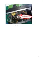
Fig.15 Heater
4.6 Power Board
In case of the failure to start, charge or the flashing of charge indicator, the power board may be
damaged. If the instrument fails to start, first check whether the cables of control board X1 and power
board X3 are plugged in. If they are plugged in, remove 4 screws on the bottom of instrument (as shown
in Fig.16) and gently pull out the base of instrument with care not to damage the cable X2, pull out
cables X2 and X3, measure whether there is 12.6V output at pins 1 and 4 of cable X3 (as shown in
Fig.17); if so, the power module is not damaged; if not, the power module is damaged, and proceed to
the determination whether the power board or battery is damaged. If the power board is damaged,
remove the screws on the power board to replace the power board.
The charge failure may be caused by the damage of battery or power board. To find out the cause, insert
the good-working battery which is fully charged into the instrument, start the system and observe the
battery icon at the upper right corner of screen, and if no lightning symbol is shown on the icon, it means
that the power board is damaged; or measure the voltage on both sides of R9 on the back of power
board, and if there is no charge voltage (less than 0.1V), the power board is damaged.
Fixing screws of
heater
Содержание 6481 Series
Страница 8: ...6 Fig 4 Jam of propel motor...
Страница 11: ...9 Fig 8 Align motor Screws of align motor...
Страница 14: ...12 Fig 11 Imaging lamp Screws fixing the imaging lamp Cable at spindle may be damaged Weld point may be broken...
Страница 16: ...14 Fig 13 Replacement of spindle...
Страница 21: ...19 Fig 18 Main control panel FPGA load indicator V17 X4 socket...


