17
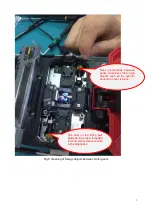
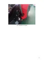
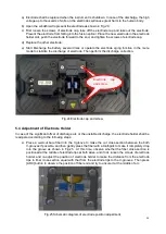
Fig.16 Removal of base
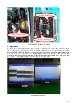
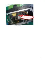
Fig.17 Power board
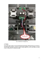
4.7 High-voltage Board
In case of no discharge, check whether the connecting cables between the high-voltage board X1 and
the control board X7 and between the high-voltage board X2 and the control board X6 is off or loose.
Make sure that the connection is normal. If the discharge failure still exists, the high-voltage board is
damaged. Replace the high-voltage board by pulling out the cables X1 and X2 of high-voltage board,
removing two high-voltage wires (on the front and back) and fixing four screws on the high-voltage board
(as shown in Fig.17). Because there are many cables passing between the high-voltage board and align
motor, be careful not to hold down the other cables when installing the high-voltage board.
Power board X3
Back
of
power
board R9
X2 cable
Содержание 6481 Series
Страница 8: ...6 Fig 4 Jam of propel motor...
Страница 11: ...9 Fig 8 Align motor Screws of align motor...
Страница 14: ...12 Fig 11 Imaging lamp Screws fixing the imaging lamp Cable at spindle may be damaged Weld point may be broken...
Страница 16: ...14 Fig 13 Replacement of spindle...
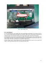
Страница 21: ...19 Fig 18 Main control panel FPGA load indicator V17 X4 socket...

