11
⑤
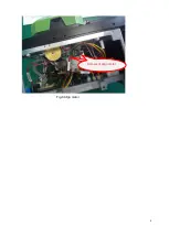
Replace it with new imaging lamp, screw down 4 screws fixing the imaging lamp, insert the
imaging lamp cable into two heat-shrink tube, and fit the imaging lamp cable into the spindle.
⑥
The heat-shrink tube on the heat-shrink imaging lamp cable is as shown in Fig.14.
⑦
Insert the pin of imaging lamp cable into the plug that has just been removed (the cable is black,
white and blue in sequence from the inside to the outside), and then insert the plug into X26
base.
⑧
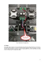
Install the sketch mounting plate.
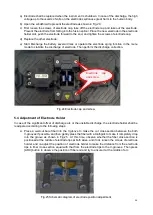
Fig.10 Sketch mounting plate
Limiting plate of sketch
mounting plate
Содержание 6481 Series
Страница 8: ...6 Fig 4 Jam of propel motor...
Страница 11: ...9 Fig 8 Align motor Screws of align motor...
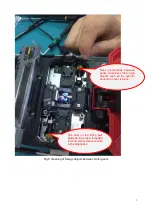
Страница 14: ...12 Fig 11 Imaging lamp Screws fixing the imaging lamp Cable at spindle may be damaged Weld point may be broken...
Страница 16: ...14 Fig 13 Replacement of spindle...
Страница 21: ...19 Fig 18 Main control panel FPGA load indicator V17 X4 socket...


