8
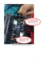
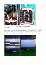
Fig. 6 Positions of propel motor screws
4.3 Align Motor
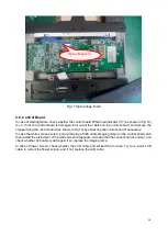
In case of the displace motor error during the normal use or the align motor error during the self-test (as
shown in Fig.7), the align motor has failed. Check the meshing between the align motor gear and the
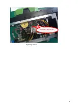
align micrometer head gear, and if it is too tight or shafts are not parallel, adjust the relative positions by
loosening the screws of align motor (see Fig.8); or if the micrometer head does not rotate smoothly,
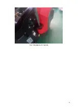
remove the align motor, and then manually toggle the micrometer head of align motor (see Fig.9) until
the rotation is smooth; if the problem still exists, replace the align motor.
Fig.7 Jam of align motor
Screw of propel motor
Screw of propel motor
Screw of propel motor
Содержание 6481 Series
Страница 8: ...6 Fig 4 Jam of propel motor...
Страница 11: ...9 Fig 8 Align motor Screws of align motor...
Страница 14: ...12 Fig 11 Imaging lamp Screws fixing the imaging lamp Cable at spindle may be damaged Weld point may be broken...
Страница 16: ...14 Fig 13 Replacement of spindle...
Страница 21: ...19 Fig 18 Main control panel FPGA load indicator V17 X4 socket...


