18
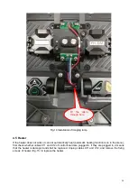
Fig.17 High-voltage board
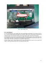
4.8. Control Board
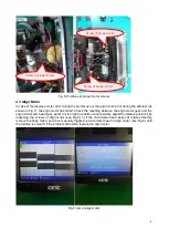
In case of starting failure, check whether the control board FPGA load indicator V17 (as shown in Fig.18)
is on. If not, the control board is damaged. Pull out all the cables on the control board, and remove the
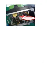
stopper fixing the control board (as shown in Fig.19) by extracting the control board if necessary.
In case the white screen at start, pull up the plug of X26 cable (imaging lamp) on the control board, and
then restart the instrument. If the white screen disappears, it means that the control board is normal, and
check whether X26 cable is damaged. If so, replace the imaging lamp.
In case of flower screen, check whether the LCD cable and socket X4 are loose. Try to re-insert LCD
cable to correct the flower screen, and if not, replace the LCD cable.
High-voltage wire
Содержание 6481 Series
Страница 8: ...6 Fig 4 Jam of propel motor...
Страница 11: ...9 Fig 8 Align motor Screws of align motor...
Страница 14: ...12 Fig 11 Imaging lamp Screws fixing the imaging lamp Cable at spindle may be damaged Weld point may be broken...
Страница 16: ...14 Fig 13 Replacement of spindle...
Страница 21: ...19 Fig 18 Main control panel FPGA load indicator V17 X4 socket...

