2
Preparation before use
2.3 Instrument Appearance
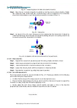
This is only a standby switch. As it is not directly connected with external power supply, it
can’t
cut off the connection between the instrument and the external power supply, and the external
power supply of the analyzer can be cut off through the power switch of the rear panel and the
connection between the analyzer and the external power supply can be completely cut off by
removing the power cord.
Fig. 2.18
【
Power On/Standby
】
key and indicator lamp
9) Test port
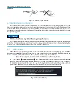
The test port is as shown in the following figure. The analyzer has two 50Ω, 3.5 mm (male) test
ports, which can be used for mutual switching between RF source and receiver, so as to measure the
device in two directions. The yellow lamp is used to indicate the source output port.
Fig. 2.19 Test Port of the Analyzer
2.3.2
Description of rear panel
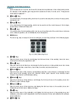
This section describes components of the rear panel of the 3672 series vector network analyzer and
their functions, as shown in the following figure.
Fig. 2.20 Rear Panel of the Network Analyzer
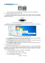
1) 10 MHz reference connector
10 Mhz reference input
10 MHz reference output
Fig. 2.21 10 MHz Reference Connector
Содержание 3672 Series
Страница 1: ...3672 Series Vector Network Analyzer Quick Start Guide ...
Страница 2: ......
Страница 7: ......


