2
Preparation before use
2.3 Instrument Appearance
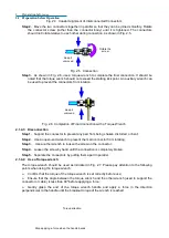
Fig. 2.32 Interface Connector of the External Test Device
The definitions and descriptions of the pin are as follows:
Table 2.5 Description of Pins of the Interface Connector of the External Test Device
Pin
Item
Functional Description
1, 15, 16, 18 (1# pin is
at the lower left corner)
Test device address
selection bit
The connection to the ground is initially low, and one
bit will be added in case of successful access to an
external device
2
Sweep wait
Trigger mode remote control sweep switch, introduce
delay mode
3 ~ 6, 9 ~ 11, 17, 19 ~
23
Address bit
AD0-AD12
Used to output data address or to receive/send data
information
7, 12
Ground wire
Reference ground wire
8
Address switch LAS
The low level indicates that the address information is
transmitted currently
24
Data switch LDS
The low level indicates that the data information is
transmitted currently
25
Read-write indication
RLW
Low level output, high level input data
13
Interruption input
Remote control reading of TTL input status
14
Not connected
Max. range: +22 V 100 mA
12)
Trigger input/output interface connector
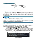
As shown in the following figure, this interface in an external and auxiliary trigger input/output
interface. The specific functions are as follows:
External trigger input - After being enabled, the vector network analyzer will be triggered by the
connector signal;
External trigger ready - After being enabled, the vector network analyzer will send a
“
Ready
”
signal to the external equipment through this interface;
Auxiliary trigger input 1/2 - After being enabled, the external equipment will send an
“
OK
”
signal to the external equipment through this connector (the external equipment is ready to receive
the trigger signal);
Auxiliary trigger input 1/2 - After being enabled and before (or after) the measurement, the
vector network analyzer will send an
“
OK
”
signal through this interface.
External
trigger
input
External
trigger
ready
Auxiliary
trigger
input 1
Auxiliary
trigger
output 1
Auxiliary
trigger
input 2
Auxiliary
trigger
output 2
Fig. 2.33 Trigger Input/Output Interface Connector
13) 28 V (BNC)
interface connector
As shown in the following figure, the BNC (female) connector can be used to drive a noise source.
Содержание 3672 Series
Страница 1: ...3672 Series Vector Network Analyzer Quick Start Guide ...
Страница 2: ......
Страница 7: ......

