2
Preparation before use
2.3 Instrument Appearance
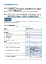
Fig. 2.24 USB Connector (the Type B/Type A Configurations are On the Left/Right Side)
5)
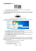
Video graphic adapter (VGA) output connector
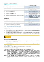
As shown in the following figure, this is a 15-pin female D-sub connector. After it is connected with
the external VGA display with the corresponding resolution, we can observe the internal and external
display at the same time.
Monitor
Fig. 2.25 Video Graphic Adapter (VGA) Output Connector
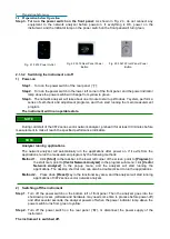
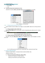
Right click the mouse on the Windows desktop and configure the multi-display mode through the
right-click menu, as shown in the following figure.
Fig. 2.26 Configuration of the Multi-display Mode
When
[Monitor]
is checked, only the external VGA display can be used to observe and display
the measurement, and the internal LCD of the analyzer has no display.
When
[Laptop]
is checked, only the internal LCD of the analyzer can be used to observe and
display the measurement, and the external VGA display has no display.
When
[Laptop]
is checked, both the internal LCD and the external VGA display can
be used to observe the measurement result.
6)
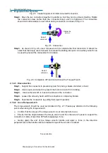
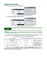
Local oscillator and RF output connector.
As shown in the following figure, the LO output and RF output is a 3.5 mm female interface
respectively. The LO output is an internal LO signal and the RF output is a source RF signal, and both of
them can be used for fault detection and millimeter-wave frequency extending. The interface
characteristics are as follows:
LO output signal frequency range: 12.535 MHz ~ 26.507606 GHz
LO output signal power range: -4 dBm ~ 6 dBm
RF output signal frequency range: 3.2 GHz ~ 26.5 GHz
RF output signal power: About 0 dBm
LO output RF output
Содержание 3672 Series
Страница 1: ...3672 Series Vector Network Analyzer Quick Start Guide ...
Страница 2: ......
Страница 7: ......

