3672 Series Vector Network Analyzer
Contents
device, fixture or cable
Frequency offset measurement
1
Used
for
frequency
offset
measurement
Mixer scalar measurement
1
Used
for
mixer
scalar
parameter measurement
Mixer vector measurement
1
Used for measurement of the
mixer vector parameter
Embedded LO measurement
1
Used for measurement of the
embedded LO converter
2D sweep and measurement of the gain compression
1
Used for 2D sweep and
measurement
of
the
gain
compression of the amplifier
Accessories:
Calibration kit
1
Used for calibration of the main
unit
Amplitude & phase stable cable (male)
1
Used for measurement of the
main unit
Amplitude & phase stable cable (female)
1
Used for measurement of the
main unit
2.1.2
Setup and installation of the instrument
To ensure the normal functions of 3672 series vector network analyzer, you should pay attention to the
following aspects:
The operating place should meet the requirements for the operating environment, heat dissipation
and electrostatic protection measures.
The placement and installation should meet the operating requirements of a desktop instrument:
The instrument should be placed horizontally on a table with an anti-static mat or supported by its
own leg.
Attention to instrument placement:
To ensure the stability and personal safety of the instrument, please select a firm and flat position to
place it, such as an anti-static table;
After the instrument is placed, it shall not be moved, and no articles can be operated or placed
under the instrument;
2.1.3
Power on/off
It is necessary to check the following items before powering on the instrument:
2.1.3.1 Connecting the power supply
Please confirm the power supply parameters and power cords before the initial charge.
Step 1. Connect the power cord:
Connect one end of the power cord supplied with the network
analyzer in the packaging box or a 3-core power cord as required to the power port on the rear
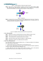
panel of the network analyzer (as shown in Fig. 2.1); the required voltage parameter is
indicated beside the power socket to remind users to use specified voltage. Connect the other
end of the power cord to a conforming AC power supply;
Step 2. Turn on the power switch of the rear panel:
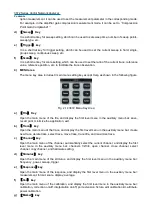
As shown in Fig. 2.2, check if the standby
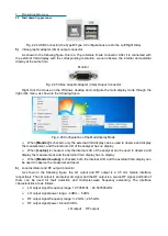
indicator lamp above the power switch of the front panel (as shown in Fig. 2.3) lights up in
yellow;
CAUTION
!
Содержание 3672 Series
Страница 1: ...3672 Series Vector Network Analyzer Quick Start Guide ...
Страница 2: ......
Страница 7: ......


