LSS-2404
29 |
P a g e
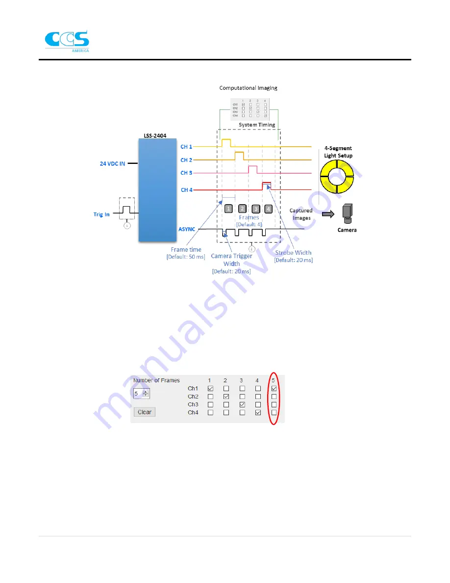
The timing diagram below illustrates the definitions described above in relation to the timing of the system.
More timing diagrams for triggering are shown in Appendix D.
Motion Correction
If the part is in motion during the multiple image capture sequence, a compensation technique called motion
correction is needed. To achieve motion correction, various techniques may be used to align the images during
the capture sequence. Check with your software vendor for the technique most suitable for your application. As
an example, one method adds an extra frame that has the same channel mapping as the first frame.
This image is considered the search image. A pattern is defined on the first image, then a search region is
defined on the search image. The search region is drawn where the defined pattern will fall in the search image.
Once the pattern is found, the algorithm determines how the part moved across the field of view during the
capture sequence and aligns the correct pixels to produce the desired Computational Imaging technique.
Be sure to set the camera’s field of view large enough
so that the part stays within the field of view during the
capture sequence. Also, be aware of the limitations of the motion correction technique. For instance, the part
may need to move straight at constant speed without rotation and not vary in size.


