


Cattron™ MP96/48 Series Portable Remote Control Systems
User Manual
52
68C-MP96/48-RD-EN
Version 006
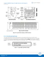
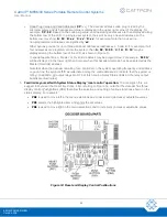
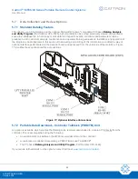
c. The red decoder board LEDs for OPR1, OPR2 and the motor watchdogs are cleared and then turned
‘ON’ as the corresponding timer expires.
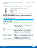
d. The decoder board System Status Display initiates a sequence of opening user information bulletins
that describe the decoder’s main features, including Cattron telephone numbers for use if technical
assistance is needed. Engineering information is also displayed.
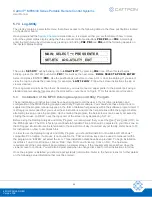
Opening bulletins include displays such as:
•
Model, revision and serial number
•
OEM supplier name
•
End user name and location
•
Programmed options, timer settings and values
4.
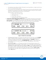
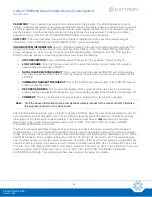
Interpret the
System Status Display default screen:
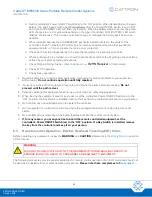
After completing the self-test cycle, the System
Status Display shows the
default
screen. This screen is displayed during normal operating conditions
with or without
a controller properly addressing the system. Referring to Figure 13, this screen contains
the following information. Note that Faults or other information will, at times, override this display.
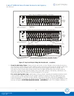
Figure 13: Default Screen Examples
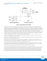
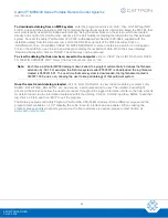
a. OFFLINE/ACTIVITY Status: This indication in the upper left corner of the display shows
‘
OFFLINE
’
when no controller is properly addressing the system. When a controller on the system operating
frequency and address is switched ‘ON’, the message will change to
‘
ACTIVITY
’
. Notice the
communication status bar to the left of the
‘
OFFLINE/ACTIVITY
’
indicator. This bar should rotate
continuously any time that power is applied to the decoder, indicating proper inter-processor
communications.
b. Main Relay Status [
M: - - - - - -
]: The upper center area of the display shows the status of the
system’s programmable main relays. For each system, up to six main relays can be used, usually to
supply power to the crane or machine’s motor controls, for example, bridge, trolley, hoist. With no
controller properly addressing the system, the display reads:
‘
M: - - - - - -
’
, signifying all main relays
‘OFF’. When a controller on the system operating frequency and address is switched ‘ON’ and all six
main relays have been programmed into the system, the message changes to
‘
M: 1 2 3 4 5 6’
.
If only the first four main relays have been programmed into the system, then the message will
indicate
‘
M:
1 2 3 4 - -
’
.


