


Cattron™ MP96/48 Series Portable Remote Control Systems
User Manual
37
68C-MP96/48-RD-EN
Version 006
5
Installation
5.1
Pre-installation Checks
Before installing the receiver/decoder, the equipment must be checked to ensure that it is working properly. The
pre-installation check is a simple test to ensure that all switches, relays, the display and the status indicators
operate properly. To accomplish this check, the receiver/decoder should be positioned on a test bench with the
appropriate input supply voltage connected to the underside of the Electronics Chassis.
Refer to the drawings provided with your system for information on which relays correspond to which controller
functions. Power up and cycle all the switches on the appropriate controller(s), observing the relay status LEDs
next to each relay as a controller function is activated. The LED should illuminate, indicating that the relay is
energized. If any of the relays do not operate properly, contact Cattron at
5.2
Interface Connections
5.2.1 Introduction
Due to the wide variety of existing control systems and the many options available, Cattron provides customized
schematic drawings for each installation. Study these drawings carefully before installing any wiring. If there are
any questions concerning the drawings or installation requirements, contact Cattron at
before proceeding. If any additions or corrections are made during the installation, note the changes on the
drawings in red ink. Return the marked-up drawings to Cattron after the installation so that final prints may be
prepared and issued.
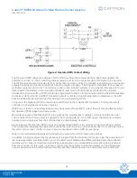
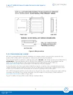
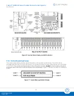
Each relay on the relay output board is completely independent of all other relays. There are no common
connections between any output contacts. This allows the connection of different power sources, AC and DC, to
each of the separate relays. The contacts are rated at 5 A, 250 VAC or 5 A, 30 VDC. All contacts are individually
fused with 250 V, 5 A fuses.
All relays have a single Normally Open contact. This contact is connected to the Terminal Block which extends
along the top of the Relay Output Board. All connections to the relays are made at this terminal block. Refer to the
drawings provided with your system for information on which relays correspond to which controller functions.
Before installing your remote control system, we advise you to finish reading this section,
in its entirety.
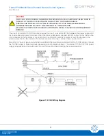
5.2.2 The Controlled Machine
The machine you are interfacing to may consist of single or multiple contactor panels, single or multiple manual
controls, single or multiple control transformers, variable frequency drives, etc. Notice that there is no common
connection between relay output contacts, allowing control of different power sources and combinations of AC
and DC power. Application of the normally open relay contacts is similar to wiring that is required for any control
switch, such as a pendant. Standard wiring practices should be observed in accordance with the National
Electrical Code, and in accordance with local codes applicable to your area.
5.2.3 Control Transformer
The power required to operate the remote control system is 115 VAC, 50-60 Hz, at less than 1 A. The remote
control system can be connected to an existing control transformer if the transformer’s size permits; otherwise, a
control transformer must be supplied to provide the appropriate power for the remote control system.


