


Cattron™ MP96/48 Series Portable Remote Control Systems
User Manual
53
68C-MP96/48-RD-EN
Version 006
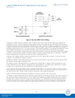
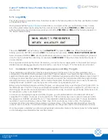
c. Code Plug Value and Valid Addresses [
CP: - -
]: The decoder address code plug is read by the
microcomputers and its hexadecimal value is displayed in the upper right corner of the display, for
example,
‘
CP: 04’
. Based on the code plug value, valid operating addresses are then displayed along
the bottom row of the LCD. In a single-user system, there will be only one valid address, so the
bottom row may show
‘
A: 04
’
,
‘
B: xx
’
,
‘
C: xx’
,
‘
D: xx
’
, for example. Note that unused (i.e.,
non-programmed) addresses are signified by
‘
xx
’
.
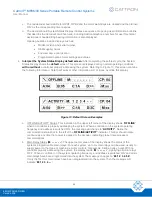
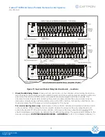
Other options provide for up to three additional addresses (addresses 2, 3 and 4). For example, if all
four addresses are programmed into the system, then
‘
A: 04
’
,
‘
B: 05
’
,
‘
C: 1A
’
,
‘
D: 3C
’
may be
displayed along the bottom row of the LCD, as shown in Figure 13.
In special applications, a ‘Master’ or ‘Override’ address may be programmed. For example,
‘
M: 0A
’
will be displayed in the lower right hand corner when this hexadecimal code has been selected as the
Master (Override) address.
Note that when the decoder is waiting for a controller on the system operating frequency and address
to go on line, the symbols
‘
>>
’
will alternate among the valid addresses to indicate that the system is
‘idling’. In addition, all output relays are OFF at this time (no Relay Status LEDs on the relay output
boards are illuminated).
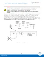
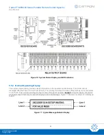
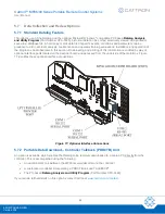
5.
Familiarize yourself with System Status Display ‘local control’ operation:
To accomplish this, we
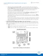
suggest that you set the Real Time Clock. First, referring to Figure 14, note that the decoder has three
display control PushButtons (PBs) that allow the selection and setting of various functions shown on the
status display. For example:
•
PB2
is used to move left in the menu selections and to decrement (decrease) adjustable values
•
PB3
selects the highlighted item and enters the set values
•
PB4
is used to move right in the menu selections and to increment (increase) adjustable values
Figure 14: Reset and Display Control Pushbuttons


