


Cattron™ MP96/48 Series Portable Remote Control Systems
User Manual
22
68C-MP96/48-RD-EN
Version 006
Typically, each motor control group is monitored by separate ASO circuits. If at any time there is a difference
between the state of the output devices and the received input command, the remote controlled equipment is
disabled via the main electrical contactor
for that specific group
. This method permits the failure in one motor
group without a shutdown of the entire system. Should this action not perform the desired shutdown, the two
mainline relays (OPR1 and OPR2) will turn off. In turn, all machine power will be disconnected.
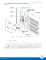
4.5.8 System Status Display
Extensive diagnostic tests are performed constantly, with operational data and faults being collected from
throughout the remote controlled system and machine. This information is displayed using a two line, 24
characters per line (2 x 24) Vacuum Fluorescent Display (VFD) located on the decoder circuit board, as viewed
through the chassis window.
These messages are available in a stacked error message queue. Any fault messages that have caused the
remote control system to ‘shut down’ are continuously displayed in turn, as a loop of bulletins. This central status
display point simplifies fault interpretation, reducing maintenance down time.
The display contains a selectable menu that allows access to the following data via three pushbuttons located on
the decoder board:
•
Viewing the Datalog
•
Setting of the real-time clock
•
Clearing the Datalog
•
Printing the Datalog
For additional information regarding the status display, please refer to the
4.5.9 Serial Communication Ports
The Cattron MP96 system decoder is available with two RS-232 ports (COM 1 and COM 3) and an isolated
RS-485 port (COM 2).
The two RS232 ports are bi-directional and are used for Datalog download via a Microsoft Windows
®
compatible
PC or laptop. The isolated RS-485 port is used to communicate with external sensing modules than can feed
back information to the decoder such as weight, speed, temperature, etc.
4.6
Standard Datalog Feature
Through the use of the Datalog and the optional
Datalog Analysis and Utility Program
(Part Number
CPA-0326), historical data can be sorted, selectively viewed, and printed or saved to a database file. A hard copy
or disk data file of specific events, conditions and parameters can be produced to aid in accident analysis,
maintenance and operator training evaluations. Installation of the program is accomplished as with any Microsoft
Windows
®
based program. Refer to the help screens of the program for details concerning its operation.
The Datalog feature consists of six different types of logged (stored) data from the MP96, as follows:
1.
Critical Systems Event Logs:
All critical
events that occur within the MP96 system are stored in a series
of datalogs. Each critical event datalog is capable of storing up to 32 entries, where these entries are
maintained on a First In-First Out (FIFO) basis. Critical systems event datalogs may be created in a
variety of categories, dependent on customer requirements. Some typical examples are: Mainline OPR,
Power Up, Reset, Watchdog Fail, E-
stop, Tilt, Online, Addresses ‘A’ through ‘D’, Address ‘M’, ASO Error,
Loop Error, Main 1 through 6, OPR Test, Bad Code Plug, RAM Fail, Datalog Command, Talkback, Bad
Address and Bad Transmit.


