


Cattron™ MP96/48 Series Portable Remote Control Systems
User Manual
87
68C-MP96/48-RD-EN
Version 006
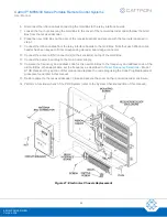
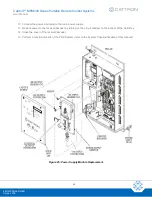
11. Connect the ribbon cable header to the relay interface board.
12. Connect the power input plug to the main power supply.
13. Close and secure the cover on the receiver/decoder enclosure.
14. As necessary, perform a functional check of the PRC System (refer to the System Checkout section of
this manual).
7.10.4 Receiver Replacement
CAUTION
ELECTROSTATIC SENSITIVE DEVICES SUCH AS EPROMS ARE PRESENT ON CIRCUIT
BOARDS. USE AN ANTI-STATIC MAT AND PERSONAL GROUNDING STRAP (WRIST) FOR ALL
MAINTENANCE PROCEDURES INVOLVING CIRCUIT BOARDS AND ELECTROSTATIC
SENSITIVE DEVICES.
FAILURE TO COMPLY WITH THIS CAUTION MAY RESULT IN EQUIPMENT DAMAGE AND WILL
VOID OUR WARRANTY.
When replacing the receiver circuit board,
the new receiver must have the same frequency as the old
receiver
. Failure to match the frequencies will result in the receiver/decoder not receiving commands from the
desired controller. Matching frequencies is accomplished by (1) verifying the EPROM part number (as discussed
in the next paragraph), and (2) setting the rotary frequency selector switch to the same position on the new
receiver as on the old receiver. Refer to the programming information provided with your customized
documentation package.
As indicated above,
the new receiver must have the same EPROM as the old receiver
. The EPROM
determines the frequency bank and contains the program for the receiver. Note and record the part number on
the label of the EPROM before replacing the receiver board. If the existing EPROM part number does not match
the EPROM part number on the replacement receiver board, contact Cattron at
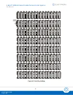
Referring to Figure 22, replace the receiver circuit board as follows:
1. Open the cover of the receiver/decoder enclosure.
2. Remove power from the e
lectronics chassis, or ‘Gold Box’, by turning off the circuit breaker on the
bottom.
3. Release the four captive screws and remove the lid from the Gold Box.
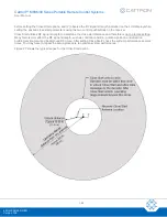
4. Note the receiver frequency by checking the EPROM part number and record the position of the rotary
frequency selector switch. The new receiver circuit board must have the same EPROM part number and
must also be set to the same frequency.
5. Disconnect the antenna lead(s) from the receiver circuit board.
6. Disconnect the power and signal wiring connector from the header CN1 on the receiver circuit board.
7. Remove the four screws and withdraw the receiver circuit board from the Gold Box pillars.
8. Set the frequency of the new receiver to the same frequency as the old receiver. This is done by
matching the EPROM part numbers and the positions of the rotary frequency selector switches.
9. Install the new receiver circuit board to the Gold Box pillars and secure with the four mounting screws.
10. Connect the power and signal wiring connector to the header CN1 on the receiver circuit board.
11. Connect the antenna lead(s) to the receiver circuit board.
!


