


7
Fig. 3 — Welcome Screen
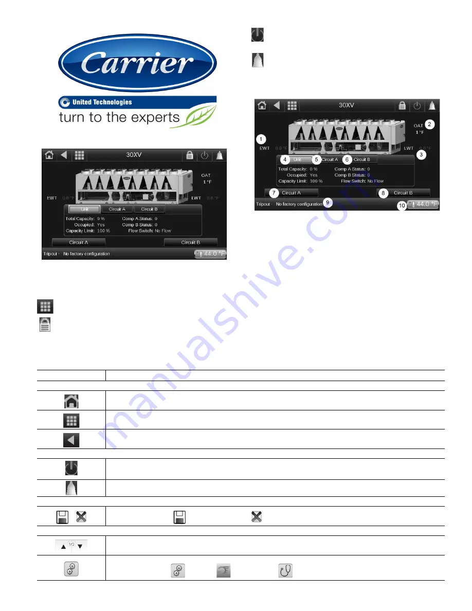
Fig. 4 — Home Screen
The following buttons appear on the top panel of the home
screen. See Table 3 for more general screen buttons.
Main Menu — Touch the Main Menu button to access all
unit functions. See Main Menu Screen on page 9 for details.
Log In — Touch to enter passwords and select language
or change the system of measurement. See page 9 for log-
in details. The icon shown is for Basic access; it changes
based on access level. See Table 3 for Advanced User,
Service, and Factory access icons.
Start/Stop — Touch to access the machine control method
menu. See page 25 for details on available operating
modes.
Alarm — The alarm icon turns solid or blinks red when a
fault is detected. See page 208 for details on system
alarms and alerts.
To display circuit specific information select the desired Cir-
cuit Button. See Fig. 5.
Fig. 5 — Home Screen with Saturated Condensing
Temperature (SCT) and Saturated Discharge
Temperature (SDT)
UNIT STATUS MESSAGE BOX
Messages may be displayed in the status bar at the bottom of
the screen relevant to the current user action. See Table 4.
Table 3 — Screen Buttons
LEGEND
1
—
Evaporator Entering Fluid Temperature
2
—
Outdoor Air Temperature
3
—
Evaporator Leaving Fluid Temperature
4
—
Unit Status
5
—
Circuit A Status
6
—
Circuit B Status
7
—
Circuit A Refrigeration Details
8
—
Circuit B Refrigeration Details
9
—
Unit Status Message
10
—
Active Setpoint
BUTTON
FUNCTION
TOP LEFT PANEL — GENERAL NAVIGATION
Home button: Goes to the home screen.
Main Menu button: Goes to the Main Menu screen from the Home screen. Allows access to unit menus and parameters. See page 9.
Back button: Goes to previous screen.
TOP RIGHT PANEL — SPECIAL NAVIGATION
Start / Stop button: Goes to the chiller start / stop screen. The Start/Stop button is gray, green, or blinking green. See the Machine Control
Methods section on page 25.
Alarm button: Goes to the alarm menu screen.The Alarm button is gray, red, or blinking red. See the Alarms and Alerts section on page 208.
BOTTOM LEFT PANEL — ACTIONS SPECIFIC TO CURRENT SCREEN OPERATION
Save/Cancel: Save button
confirms changes. Cancel
discards changes.
BOTTOM RIGHT PANEL — SCROLLING INSIDE CURRENT SCREEN
Up and Down arrows: Scroll within screen content. A page indicator shows what page is being viewed, and the total number of pages.
Troubleshoot Quick Test and Svc Alerts: only appears in Service or Factory Access Level. Touching the icon opens three icons on the side of
the screen: Service Alerts
. Quick Test
. and Troubleshoot
30 5927
30 592
Содержание AquaForce 30XV140
Страница 79: ...79 Fig 76 VFD Communication Wiring Compressor A B Fan VFD A1 A2 B1 B2...
Страница 82: ...82 Fig 81 VFD Compressor Locations 30XV225 325 30XV350 500 30XV140 325 COMPRESSOR A VFD COMPRESSOR B VFD...
Страница 228: ...228 Fig 90 30XV Typical Field Wiring Schematic cont...
Страница 229: ...229 Fig 91 30XV Standard Tier 140 275 All Voltages Power Schematic NOTE See Legend on page 226...
Страница 230: ...230 Fig 92 30XV Standard Tier 300 325 All Voltages Power Schematic NOTE See Legend on page 226...
Страница 231: ...231 Fig 92 30XV Standard Tier 300 325 All Voltages Power Schematic cont NOTE See Legend on page 226...
Страница 232: ...232 Fig 93 30XV Standard Tier 350 500 380 400 415 440 460 575v Power Schematic NOTE See Legend on page 226...
Страница 233: ...233 Fig 93 30XV Standard Tier 350 500 380 400 415 440 460 575v Power Schematic cont NOTE See Legend on page 226...
Страница 234: ...234 Fig 94 30XV High Tier 350 450 All Voltages Mid Tier 350 500 All Voltages Power Schematic NOTE See Legend on page 226...
Страница 235: ...235 Fig 95 30XV Mid Tier 140 All Voltages 160 275 380 400 415 440 460 575v Power Schematic NOTE See Legend on page 226...
Страница 236: ...236 Fig 96 30XV High Tier 140 200 380 400 415 440 460 575v Power Schematic NOTE See Legend on page 226...
Страница 237: ...237 Fig 97 30XV High Tier 140 200 208 230v Mid Tier 160 200 208 230v Power Schematic NOTE See Legend on page 226...
Страница 238: ...238 Fig 98 30XV High Tier 225 325 All Voltages Mid Tier 300 325 All Voltages Power Schematic NOTE See Legend on page 226...
Страница 240: ...240 Fig 99 30XV Communication Wiring...
Страница 241: ...241 Fig 100 30XV 115V Control Wiring All Tonnages All Voltages...
Страница 242: ...242 Fig 101 30XV 24V Control Wiring 30XV140 325 All Voltages...
Страница 243: ...243 Fig 101 30XV 24V Control Wiring 30XV140 325 All Voltages cont...
Страница 244: ...244 Fig 102 30XV 24V Control Wiring 30XV350 500 All Voltages...
Страница 245: ...245 Fig 102 30XV 24V Control Wiring 30XV350 500 All Voltages cont...
Страница 246: ...246 Fig 103 Component Arrangement Diagram for 30XV140 325...
Страница 247: ...247 Fig 103 Component Arrangement Diagram for 30XV140 325 cont...
Страница 248: ...248 Fig 104 Component Arrangement Diagram for 30XV350 500...
Страница 337: ...337 APPENDIX J FACTORY SUPPLIED PUMPS cont Fig L System Information...
Страница 338: ...338 APPENDIX J FACTORY SUPPLIED PUMPS cont Fig M Unit and Language Settings...
Страница 339: ...339 APPENDIX J FACTORY SUPPLIED PUMPS cont Fig N Hand Off Auto This is set in Auto mode for sensorless operation...
Страница 341: ...341 APPENDIX J FACTORY SUPPLIED PUMPS cont Fig P Data Input 2...
Страница 342: ...342 APPENDIX J FACTORY SUPPLIED PUMPS cont Fig Q Data Input 3...
Страница 347: ...347 APPENDIX J FACTORY SUPPLIED PUMPS cont Fig U Pump Wiring Diagram...


