


11
Fig. 11 — General Configuration
Touch the field corresponding to the parameter to be modified
and make the necessary changes. When all necessary changes
have been made, touch the Save button
to confirm or the
Cancel button
to cancel changes. For a complete list of
general parameters, see Appendix A.
TRENDING SCREEN
The Trend Display screen allows for easy monitoring of parame-
ters selected by the user. To access the Trend Display screen, se-
lect Trend Display
on the Main Menu. See Fig. 12.
Fig. 12 — Trend Display Screen
Select the parameters to be displayed by selecting the box to the
left of the parameter name. The scroll bar on the right of the screen
can be used to see all possible selections; to save a selection touch
the Save Trend Display Options Button. Once the parameters to be
trended are selected and saved, touch the Display Trend Log But-
ton and the trend graph will be displayed. See Fig. 13.
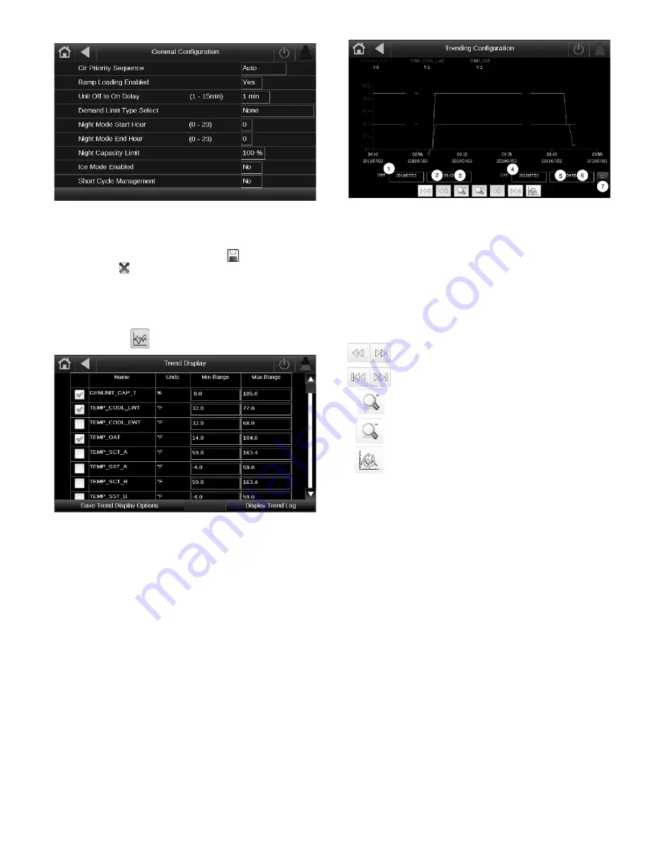
Fig. 13 — Trending Configuration Screen
Use the following buttons to adjust the Trendings display:
MENU ARCHITECTURE
See Fig. 14-16 for Carrier Controller menu structure. The op-
tions displayed depend on the user’s access level as shown in
the figures. The user can navigate through the Carrier Control-
ler display screens by selecting the buttons that appear on the
screen. When a button is selected, either a submenu or a list of
parameters and values will be shown. If the list of parameters
and values is shown, the top line of the display will show either the
menu item name if sub-menu items appear or the table name when
points and values are displayed. Selecting an item will cause a
Point Data dialog box to appear. For a complete list of tables and
points with display names and CCN point names, see Appendixes
A and B.
SETTING TIME AND DATE
The date and time for the controls can be set by opening the
Main
Menu
Configuration Menu
HMI Configuration Menu
Date/Time Configuration
. Select either the NETWORK TIME
SYNC button or SET TIME MANUALLY button. Choosing the
NETWORK TIME SYNC button will allow the controller to syn-
chronize the time with a network server if the chiller control sys-
tem is connected to a network. See Appendix A, page 258. See
Fig. 17 for details required to use Network Time Sync. Selecting
SET TIME MANUALLY button allows the user to configure the
Time Zone and set the date, time, daylight saving time, and wheth-
er today or tomorrow is a holiday. See Fig. 17 for details.
30 5927
Navigate across the time line.
Go to beginning or end of selected period.
Zoom in to magnify the view.
Zoom out to expand the viewed area.
Refresh (reload) data.
LEGEND
1
—
Set the start date
2
—
Set the start hour
3
—
Set the start minutes
4
—
Set the end date
5
—
Set the end hour
6
—
Set the end minutes
7
—
Select Go to graph
a30 5926
Содержание AquaForce 30XV140
Страница 79: ...79 Fig 76 VFD Communication Wiring Compressor A B Fan VFD A1 A2 B1 B2...
Страница 82: ...82 Fig 81 VFD Compressor Locations 30XV225 325 30XV350 500 30XV140 325 COMPRESSOR A VFD COMPRESSOR B VFD...
Страница 228: ...228 Fig 90 30XV Typical Field Wiring Schematic cont...
Страница 229: ...229 Fig 91 30XV Standard Tier 140 275 All Voltages Power Schematic NOTE See Legend on page 226...
Страница 230: ...230 Fig 92 30XV Standard Tier 300 325 All Voltages Power Schematic NOTE See Legend on page 226...
Страница 231: ...231 Fig 92 30XV Standard Tier 300 325 All Voltages Power Schematic cont NOTE See Legend on page 226...
Страница 232: ...232 Fig 93 30XV Standard Tier 350 500 380 400 415 440 460 575v Power Schematic NOTE See Legend on page 226...
Страница 233: ...233 Fig 93 30XV Standard Tier 350 500 380 400 415 440 460 575v Power Schematic cont NOTE See Legend on page 226...
Страница 234: ...234 Fig 94 30XV High Tier 350 450 All Voltages Mid Tier 350 500 All Voltages Power Schematic NOTE See Legend on page 226...
Страница 235: ...235 Fig 95 30XV Mid Tier 140 All Voltages 160 275 380 400 415 440 460 575v Power Schematic NOTE See Legend on page 226...
Страница 236: ...236 Fig 96 30XV High Tier 140 200 380 400 415 440 460 575v Power Schematic NOTE See Legend on page 226...
Страница 237: ...237 Fig 97 30XV High Tier 140 200 208 230v Mid Tier 160 200 208 230v Power Schematic NOTE See Legend on page 226...
Страница 238: ...238 Fig 98 30XV High Tier 225 325 All Voltages Mid Tier 300 325 All Voltages Power Schematic NOTE See Legend on page 226...
Страница 240: ...240 Fig 99 30XV Communication Wiring...
Страница 241: ...241 Fig 100 30XV 115V Control Wiring All Tonnages All Voltages...
Страница 242: ...242 Fig 101 30XV 24V Control Wiring 30XV140 325 All Voltages...
Страница 243: ...243 Fig 101 30XV 24V Control Wiring 30XV140 325 All Voltages cont...
Страница 244: ...244 Fig 102 30XV 24V Control Wiring 30XV350 500 All Voltages...
Страница 245: ...245 Fig 102 30XV 24V Control Wiring 30XV350 500 All Voltages cont...
Страница 246: ...246 Fig 103 Component Arrangement Diagram for 30XV140 325...
Страница 247: ...247 Fig 103 Component Arrangement Diagram for 30XV140 325 cont...
Страница 248: ...248 Fig 104 Component Arrangement Diagram for 30XV350 500...
Страница 337: ...337 APPENDIX J FACTORY SUPPLIED PUMPS cont Fig L System Information...
Страница 338: ...338 APPENDIX J FACTORY SUPPLIED PUMPS cont Fig M Unit and Language Settings...
Страница 339: ...339 APPENDIX J FACTORY SUPPLIED PUMPS cont Fig N Hand Off Auto This is set in Auto mode for sensorless operation...
Страница 341: ...341 APPENDIX J FACTORY SUPPLIED PUMPS cont Fig P Data Input 2...
Страница 342: ...342 APPENDIX J FACTORY SUPPLIED PUMPS cont Fig Q Data Input 3...
Страница 347: ...347 APPENDIX J FACTORY SUPPLIED PUMPS cont Fig U Pump Wiring Diagram...


