


92
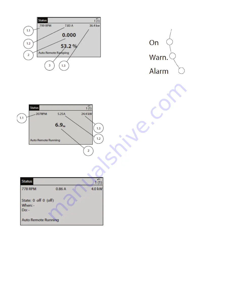
Fig. 84 — Status Display I
Status Display II shows the operating variables 1.1, 1.2, 1.3
and 2. In the example shown in Fig. 85, Speed, Motor Current,
Motor Power, and Frequency are selected as variables in the
first and second lines. Variables 1.1, 1.2, and 1.3 are shown in
small size. Variable 2 is shown in large size.
Fig. 85 — Status Display II
Status Display III shows events and actions of the Smart Logic
Control. Figure 86 shows an example.
Fig. 86 — Status Display III
The operator can adjust the display brightness by touching Sta-
tus and
▲
to darken the display or
▼
to lighten it.
Indicator lights (LEDs) indicate whether the unit is on and if
there are any warning or alarm conditions:
• Green LED (On): Control section is working. The On LED
is activated when the VFD receives power from mains
voltage, a DC bus terminal, or an external 24 V supply. At
the same time, the back light is on.
• Yellow LED (Warn.): Indicates a warning.
• Flashing Red LED (Alarm): Indicates an alarm.
The warning and/or alarm LEDs light up if certain threshold
values are exceeded. A status message and alarm text also ap-
pear on the control panel. See Fig. 87.
Fig. 87 — Indicator Lights
The menu keys below the display and indicator lights include
Status, Quick Menu, Main Menu, and Alarm Log. The Status
menu indicates the status of the frequency converter and/or the
motor. Three display modes are available (see Fig. 84-86). Use
the Status key for selecting mode of display or for changing
back to display mode from the Quick Menu Mode, the Main
Menu Mode, or the Alarm Log mode. The operator can also
use the Status key to toggle between single or double read-out
mode.
The Quick Menu key allows quick set-up of the frequency con-
verter. The most common HVAC functions can be programmed
here. Menu options include:
• My Personal Menu
• Quick Set-up
• Function Set-up
• Changes Made
• Loggings
The Function Set-up option provides quick and easy access to
all parameters required for most HVAC applications. Among
other features it also includes parameters for selecting which
variables to display on the local control panel, digital preset
speeds, scaling of analog references, closed loop single-zone
and multi-zone applications, and specific functions related to
fans, pumps and compressors.
The Quick Menu parameters can be accessed immediately un-
less a password has been created via 0-60 Main Menu Pass-
word, 0-61 Access to Main Menu without Password, 0-65 Per-
sonal Menu Password, or 0-66 Access to Personal Menu with-
out Password. It is possible to switch directly between Quick
Menu mode and Main Menu mode.
The Main Menu key is used for programming all parameters.
These can be accessed immediately unless a password has been
created via 0-60 Main Menu Password, 0-61 Access to Main
Menu without Password, 0-65 Personal Menu Password, or 0-
66 Access to Personal Menu without Password. For most
HVAC applications it is not necessary to access the Main Menu
parameters but instead use the Quick Menu. Quick Set-up and
Function Set-up provides the simplest and quickest access to
the typical required parameters.
It is possible to switch directly between Main Menu mode and
Quick Menu mode. The parameter shortcut can be carried out
by touching the Main Menu key for 3 seconds. The parameter
shortcut allows direct access to any parameter.
Touch Alarm Log to display a list of the 10 latest alarms (num-
bered A1-A10). To obtain additional details about an alarm,
touch the navigation keys to reach the alarm number and touch
OK. Information is displayed about the condition of the fre-
quency converter before it enters the alarm mode. The Alarm
Log key also provides access to a Maintenance log.
a30-5857
a30-5935
30 5859
a30-5856
Содержание AquaForce 30XV140
Страница 79: ...79 Fig 76 VFD Communication Wiring Compressor A B Fan VFD A1 A2 B1 B2...
Страница 82: ...82 Fig 81 VFD Compressor Locations 30XV225 325 30XV350 500 30XV140 325 COMPRESSOR A VFD COMPRESSOR B VFD...
Страница 228: ...228 Fig 90 30XV Typical Field Wiring Schematic cont...
Страница 229: ...229 Fig 91 30XV Standard Tier 140 275 All Voltages Power Schematic NOTE See Legend on page 226...
Страница 230: ...230 Fig 92 30XV Standard Tier 300 325 All Voltages Power Schematic NOTE See Legend on page 226...
Страница 231: ...231 Fig 92 30XV Standard Tier 300 325 All Voltages Power Schematic cont NOTE See Legend on page 226...
Страница 232: ...232 Fig 93 30XV Standard Tier 350 500 380 400 415 440 460 575v Power Schematic NOTE See Legend on page 226...
Страница 233: ...233 Fig 93 30XV Standard Tier 350 500 380 400 415 440 460 575v Power Schematic cont NOTE See Legend on page 226...
Страница 234: ...234 Fig 94 30XV High Tier 350 450 All Voltages Mid Tier 350 500 All Voltages Power Schematic NOTE See Legend on page 226...
Страница 235: ...235 Fig 95 30XV Mid Tier 140 All Voltages 160 275 380 400 415 440 460 575v Power Schematic NOTE See Legend on page 226...
Страница 236: ...236 Fig 96 30XV High Tier 140 200 380 400 415 440 460 575v Power Schematic NOTE See Legend on page 226...
Страница 237: ...237 Fig 97 30XV High Tier 140 200 208 230v Mid Tier 160 200 208 230v Power Schematic NOTE See Legend on page 226...
Страница 238: ...238 Fig 98 30XV High Tier 225 325 All Voltages Mid Tier 300 325 All Voltages Power Schematic NOTE See Legend on page 226...
Страница 240: ...240 Fig 99 30XV Communication Wiring...
Страница 241: ...241 Fig 100 30XV 115V Control Wiring All Tonnages All Voltages...
Страница 242: ...242 Fig 101 30XV 24V Control Wiring 30XV140 325 All Voltages...
Страница 243: ...243 Fig 101 30XV 24V Control Wiring 30XV140 325 All Voltages cont...
Страница 244: ...244 Fig 102 30XV 24V Control Wiring 30XV350 500 All Voltages...
Страница 245: ...245 Fig 102 30XV 24V Control Wiring 30XV350 500 All Voltages cont...
Страница 246: ...246 Fig 103 Component Arrangement Diagram for 30XV140 325...
Страница 247: ...247 Fig 103 Component Arrangement Diagram for 30XV140 325 cont...
Страница 248: ...248 Fig 104 Component Arrangement Diagram for 30XV350 500...
Страница 337: ...337 APPENDIX J FACTORY SUPPLIED PUMPS cont Fig L System Information...
Страница 338: ...338 APPENDIX J FACTORY SUPPLIED PUMPS cont Fig M Unit and Language Settings...
Страница 339: ...339 APPENDIX J FACTORY SUPPLIED PUMPS cont Fig N Hand Off Auto This is set in Auto mode for sensorless operation...
Страница 341: ...341 APPENDIX J FACTORY SUPPLIED PUMPS cont Fig P Data Input 2...
Страница 342: ...342 APPENDIX J FACTORY SUPPLIED PUMPS cont Fig Q Data Input 3...
Страница 347: ...347 APPENDIX J FACTORY SUPPLIED PUMPS cont Fig U Pump Wiring Diagram...


