


35
DUAL CHILLER PUMP CONTROL FOR PARALLEL
CHILLER APPLICATIONS
Parallel chiller control with dedicated pumps is recommended.
The chiller must start and stop its own water pump located in
its own piping. If pumps are not dedicated for each chiller’s
piping, chiller isolation valves are required; each chiller must
open and close its own isolation valve through the control. Fig-
ures 32-35 show typical pump arrangements for dual chiller
parallel applications.
Although not recommended, it is possible to configure the sys-
tem with no individual pump control. In applications where the
unit is configured for fresh water (
Main Menu
Configura-
tion Menu
Service Parameters, Evaporator Fluid Type=1
[Fresh Water]
), and Set Point temperature is close to the lower
limit of the fresh water range, it is possible for changeable
leaving water conditions as the chilled water flow rate drops to
an operating unit, causing the leaving chilled water tempera-
ture to drop and initiate the evaporator freeze protection over-
ride. Constant flow applications may alleviate this issue.
In constant water flow applications, the master chiller should
be the primary control source for the chilled water pump. The
slave chiller should have override capability. In the event of a
communication failure between the master and slave chillers,
the slave chiller will operate as a stand-alone machine and
therefore must be able to enable the chilled water pump.
DUAL CHILLER CONTROL FOR SERIES CHILLER
APPLICATIONS
When chillers are configured to work in series mode no addi-
tional chilled water supply sensor is required. The master
chiller will be installed downstream of the slave chiller (the
slave chiller outlet fluid is the master inlet fluid). If pump con-
trol is required, it will be controlled by the master chiller.
To configure the master chiller for series applications, see Ta-
ble 28. To configure the slave chiller for series applications,
see Table 29.
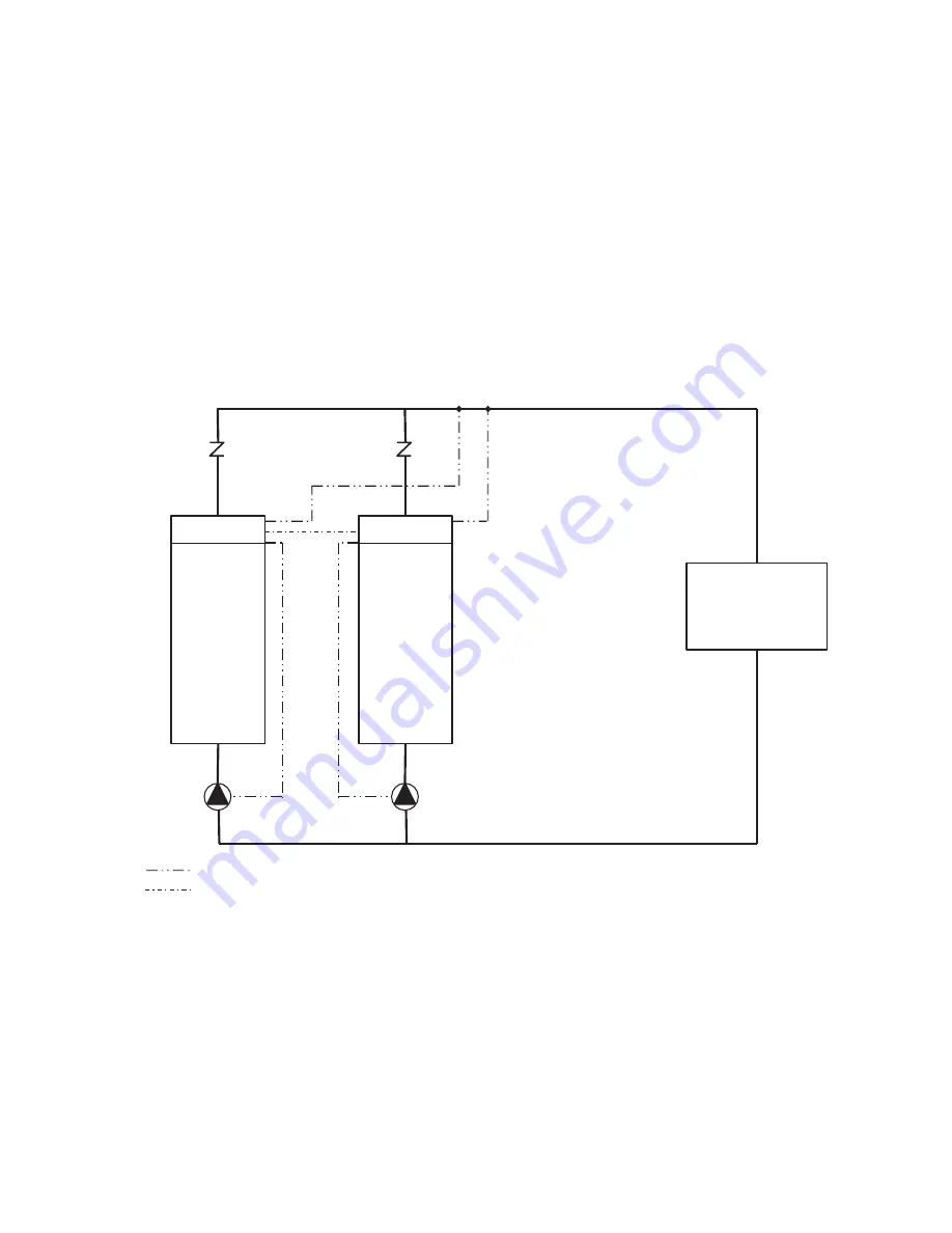
Fig. 32 — Typical Parallel Master/Slave Chillers
Dedicated Primary Pumping, Variable Flow, Leaving Water Control
CONTROL BOX
SLAVE
CHILLER
CONTROL BOX
MASTER
CHILLER
LOAD
CHECK VALVES
CHWS TEMP SENSORS
FIELD WIRING
FIELD COMMUNICATION WIRING
SLAVE
PUMP
MASTER
PUMP
NOTE: This is a simplified piping diagram.
Not all hydronic specialties are shown.
Содержание AquaForce 30XV140
Страница 79: ...79 Fig 76 VFD Communication Wiring Compressor A B Fan VFD A1 A2 B1 B2...
Страница 82: ...82 Fig 81 VFD Compressor Locations 30XV225 325 30XV350 500 30XV140 325 COMPRESSOR A VFD COMPRESSOR B VFD...
Страница 228: ...228 Fig 90 30XV Typical Field Wiring Schematic cont...
Страница 229: ...229 Fig 91 30XV Standard Tier 140 275 All Voltages Power Schematic NOTE See Legend on page 226...
Страница 230: ...230 Fig 92 30XV Standard Tier 300 325 All Voltages Power Schematic NOTE See Legend on page 226...
Страница 231: ...231 Fig 92 30XV Standard Tier 300 325 All Voltages Power Schematic cont NOTE See Legend on page 226...
Страница 232: ...232 Fig 93 30XV Standard Tier 350 500 380 400 415 440 460 575v Power Schematic NOTE See Legend on page 226...
Страница 233: ...233 Fig 93 30XV Standard Tier 350 500 380 400 415 440 460 575v Power Schematic cont NOTE See Legend on page 226...
Страница 234: ...234 Fig 94 30XV High Tier 350 450 All Voltages Mid Tier 350 500 All Voltages Power Schematic NOTE See Legend on page 226...
Страница 235: ...235 Fig 95 30XV Mid Tier 140 All Voltages 160 275 380 400 415 440 460 575v Power Schematic NOTE See Legend on page 226...
Страница 236: ...236 Fig 96 30XV High Tier 140 200 380 400 415 440 460 575v Power Schematic NOTE See Legend on page 226...
Страница 237: ...237 Fig 97 30XV High Tier 140 200 208 230v Mid Tier 160 200 208 230v Power Schematic NOTE See Legend on page 226...
Страница 238: ...238 Fig 98 30XV High Tier 225 325 All Voltages Mid Tier 300 325 All Voltages Power Schematic NOTE See Legend on page 226...
Страница 240: ...240 Fig 99 30XV Communication Wiring...
Страница 241: ...241 Fig 100 30XV 115V Control Wiring All Tonnages All Voltages...
Страница 242: ...242 Fig 101 30XV 24V Control Wiring 30XV140 325 All Voltages...
Страница 243: ...243 Fig 101 30XV 24V Control Wiring 30XV140 325 All Voltages cont...
Страница 244: ...244 Fig 102 30XV 24V Control Wiring 30XV350 500 All Voltages...
Страница 245: ...245 Fig 102 30XV 24V Control Wiring 30XV350 500 All Voltages cont...
Страница 246: ...246 Fig 103 Component Arrangement Diagram for 30XV140 325...
Страница 247: ...247 Fig 103 Component Arrangement Diagram for 30XV140 325 cont...
Страница 248: ...248 Fig 104 Component Arrangement Diagram for 30XV350 500...
Страница 337: ...337 APPENDIX J FACTORY SUPPLIED PUMPS cont Fig L System Information...
Страница 338: ...338 APPENDIX J FACTORY SUPPLIED PUMPS cont Fig M Unit and Language Settings...
Страница 339: ...339 APPENDIX J FACTORY SUPPLIED PUMPS cont Fig N Hand Off Auto This is set in Auto mode for sensorless operation...
Страница 341: ...341 APPENDIX J FACTORY SUPPLIED PUMPS cont Fig P Data Input 2...
Страница 342: ...342 APPENDIX J FACTORY SUPPLIED PUMPS cont Fig Q Data Input 3...
Страница 347: ...347 APPENDIX J FACTORY SUPPLIED PUMPS cont Fig U Pump Wiring Diagram...


