


344
APPENDIX J — FACTORY-SUPPLIED PUMPS (cont)
Control Mode: Set to “Parallel”.
Operational Mode: Set to “Quad Pressure Min Flow”.
Id: This is a number, 1-4 depending on number of pumps, to
identify each pump. It will be different for each pump. The
pump identified as 1 will be the master. Make this the furthest
left pump looking at the displays.
BEP: This is the “Best Efficiency Point” for a single pump. It is
set from the factory and does not need to be adjusted.
Maximum Operating Pump Count: Enter the number of pumps
in the chiller.
Total Design Flow and Total Minimum Flow: Values are calcu-
lated from the design flows below and the Maximum Operat-
ing Pump Count. This is what the chiller will see.
Operational Limits: Set as “Standard”.
Design Flow: Enter the system design flow divided by the
number of pumps.
Design Head: Enter the system design head for the pump. Use
the total head including the building and chiller.
Zero Flow Head: Enter 40% of the design head.
Min Flow: Enter the min flow divided by the number of
pumps. Assure the Total Minimum Flow shown above is high-
er than the chiller specified minimum. If value is not available,
enter chiller nominal size times 1.5, divided by the number of
pumps.
Once selections are made, touch the “Update” button at the
bottom left of this section.
If wireless connection cannot be made, the following procedure
can be used on a temporary basis to get the pumps running.
1. Using the manual mode on the pump, set the pumps to run at
design flow. If this value is not available, use the nominal
flow of the chiller, 2.4 * tons. The flow is per pump so set
each pump to the design flow divided by the number of
pumps used to meet the load. For the N+0 option, use the
number of pumps. For the N+1 option, use the number of
pumps minus one.
2. Record the head pressure at the design flow from the display.
3. Using the manual mode on the pump, set the pumps to run at
minimum flow. Assure this is above the rated minimum flow
of the chiller.
4. Record the head pressure at the minimum flow from the
display.
5. Set these values at the pump display. Go to Pump Configura-
tion/Pump Control/Parallel/Quadratic. Enter the design flow.
Enter the design head pressure and minimum head pressure
recorded from the steps above.
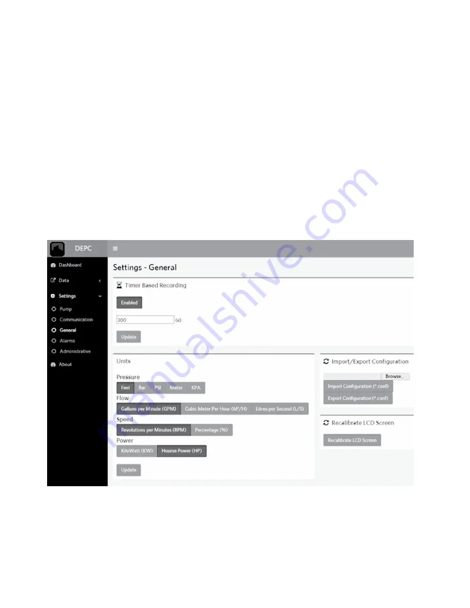
Fig. S — General Settings
Содержание AquaForce 30XV140
Страница 79: ...79 Fig 76 VFD Communication Wiring Compressor A B Fan VFD A1 A2 B1 B2...
Страница 82: ...82 Fig 81 VFD Compressor Locations 30XV225 325 30XV350 500 30XV140 325 COMPRESSOR A VFD COMPRESSOR B VFD...
Страница 228: ...228 Fig 90 30XV Typical Field Wiring Schematic cont...
Страница 229: ...229 Fig 91 30XV Standard Tier 140 275 All Voltages Power Schematic NOTE See Legend on page 226...
Страница 230: ...230 Fig 92 30XV Standard Tier 300 325 All Voltages Power Schematic NOTE See Legend on page 226...
Страница 231: ...231 Fig 92 30XV Standard Tier 300 325 All Voltages Power Schematic cont NOTE See Legend on page 226...
Страница 232: ...232 Fig 93 30XV Standard Tier 350 500 380 400 415 440 460 575v Power Schematic NOTE See Legend on page 226...
Страница 233: ...233 Fig 93 30XV Standard Tier 350 500 380 400 415 440 460 575v Power Schematic cont NOTE See Legend on page 226...
Страница 234: ...234 Fig 94 30XV High Tier 350 450 All Voltages Mid Tier 350 500 All Voltages Power Schematic NOTE See Legend on page 226...
Страница 235: ...235 Fig 95 30XV Mid Tier 140 All Voltages 160 275 380 400 415 440 460 575v Power Schematic NOTE See Legend on page 226...
Страница 236: ...236 Fig 96 30XV High Tier 140 200 380 400 415 440 460 575v Power Schematic NOTE See Legend on page 226...
Страница 237: ...237 Fig 97 30XV High Tier 140 200 208 230v Mid Tier 160 200 208 230v Power Schematic NOTE See Legend on page 226...
Страница 238: ...238 Fig 98 30XV High Tier 225 325 All Voltages Mid Tier 300 325 All Voltages Power Schematic NOTE See Legend on page 226...
Страница 240: ...240 Fig 99 30XV Communication Wiring...
Страница 241: ...241 Fig 100 30XV 115V Control Wiring All Tonnages All Voltages...
Страница 242: ...242 Fig 101 30XV 24V Control Wiring 30XV140 325 All Voltages...
Страница 243: ...243 Fig 101 30XV 24V Control Wiring 30XV140 325 All Voltages cont...
Страница 244: ...244 Fig 102 30XV 24V Control Wiring 30XV350 500 All Voltages...
Страница 245: ...245 Fig 102 30XV 24V Control Wiring 30XV350 500 All Voltages cont...
Страница 246: ...246 Fig 103 Component Arrangement Diagram for 30XV140 325...
Страница 247: ...247 Fig 103 Component Arrangement Diagram for 30XV140 325 cont...
Страница 248: ...248 Fig 104 Component Arrangement Diagram for 30XV350 500...
Страница 337: ...337 APPENDIX J FACTORY SUPPLIED PUMPS cont Fig L System Information...
Страница 338: ...338 APPENDIX J FACTORY SUPPLIED PUMPS cont Fig M Unit and Language Settings...
Страница 339: ...339 APPENDIX J FACTORY SUPPLIED PUMPS cont Fig N Hand Off Auto This is set in Auto mode for sensorless operation...
Страница 341: ...341 APPENDIX J FACTORY SUPPLIED PUMPS cont Fig P Data Input 2...
Страница 342: ...342 APPENDIX J FACTORY SUPPLIED PUMPS cont Fig Q Data Input 3...
Страница 347: ...347 APPENDIX J FACTORY SUPPLIED PUMPS cont Fig U Pump Wiring Diagram...


