background image

Model 702G/O Advanced gas/oil burners — Instruction manual

Carlin part number MN702GO Rev. 06/23/14

– 8 –

Where appliance instructions differ from this manual, follow the appliance instructions.

Prepare the appliance

  Burner input: Install a burner sized for the normal input rat-

ing of the appliance. Do not install a burner with a higher 

firing rate than the appliance rating. Do not install a burner 

with a firing rate more than 10% lower than the appliance 

rating. The appliance and vent system could be damaged 

due to condensation.


Clean the appliance: Clean the appliance thoroughly. Test 

all electrical components and verify the relief valve works 

(boilers only).


Seal the appliance: Seal all flue-gas containing joints.  Seal 

all connections to the vent piping or breeching.


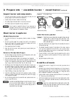
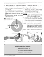
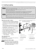
Verify combustion chamber dimensions comply with the 

minimum dimensions recommended on page 9. Install or 

replace chamber liner if required by the appliance manu-

facturer. The burner must not extend into the combustion 

chamber. The end of the burner air tube must be within ¼" 

of the inside face of the chamber. If the space around the 

burner air tube is more than ¼", wrap the burner air tube 

with minimum 2300-°F-rated ceramic fiber blanket to seal 

off the gap. 


Repair or replace damaged appliance components. Inspect 

the appliance thoroughly. Follow appliance manufacturer’s 

guidelines for repair or replacement of any component found 

defective.


When cleaning the appliance or working with ceramic fiber 

refractories or fiberglass insulation, see WARNING on this 

page.


Failure to comply with the above could result in severe 

personal injury, death or substantial property damage.

Prepare appliance for burner mounting

  Positive overfire pressure applications: When firing with 

positive overfire pressure, do not exceed the pressure 

specified in the appliance manual.


Positive overfire pressure reduces maximum burner capac-

ity. See Page 3 for estimated reduction in burner capacity 

with pressurized firing and high altitude applications.


Failure to comply could result in severe personal injury, 

death or substantial property damage.

Ceramic fiber or 

Fiberglass insulation

  Ceramic fiber materials, such as chamber liners, 

may contain carcinogenic particles (chrystobalites) 
after exposure to heat. Airborne particles from 
fiberglass or ceramic fiber components have been 
listed as potentially carcinogenic by the State of 
California. Take the following precautions when 
removing, replacing and handling these items.


Avoid breathing dust and avoid contact with 
skin or eyes
. Wear long-sleeved, loose-fitting 
clothing, gloves and eye protection. Use a NIOSH 
N95 certified respirator. This respirator  meets 
requirements for protection from chrystobalites. 
Actual job requirements or NIOSH regulations 
may  require  other  or  additional  protection. 
For  information,  refer  to  the  NIOSH  website, 
http://www.cdc.gov/niosh/homepage.html.


Ceramic fiber removal: To prevent airborne dust, 
thoroughly wet ceramic fiber with water before 
handling. Place ceramic fiber materials in a plastic 
bag and seal to dispose.


Avoid blowing, tearing, sawing or spraying fiber-
glass or ceramic fiber materials. If such operations 
are necessary, wear extra protection to prevent 
breathing dust.


Wash work clothes separately from other laun-
dry
. Rinse clothes washer thoroughly afterwards 
to prevent contamination of other clothing.


NIOSH First aid procedures:


Eye exposure — irrigate immediately


Breathing — fresh air.

2.  Prepare site  •  assemble burner  •  mount burner 

(continued)

Содержание 702G/O

Страница 1: ...stantial property damage USER Refer only to User care and maintenance on back page for information regarding operation of this burner The burner Instruction Manual is intended only for your service te...

Страница 2: ...uidelinesbelowtoavoidpotentialsevere personal injury death or substantial property dam age Installer service technician Read all instructions before proceeding Perform all procedures and in the order...

Страница 3: ...n of Domestic Gas Conversion Burners ANSI Z21 8 National Fuel Gas Code ANSI Z223 1 NFPA 54 Standard for the Installation of Oil Burning Equipment NFPA 31 National Electrical Code ANSI NFPA 70 All addi...

Страница 4: ...firing Then gas flow is adjusted to match the air flow at low and high fire rates See the Starting and operating section of this manual for the complete description of the adjustment process The foll...

Страница 5: ...d assembly 22 Oil valve junction box 23 1st stage oil valve 24 Safety oil valve 25 2nd stage oil valve fuel unit blocking valve 29 Gas manifold 30 Gas spuds 4 required 31 Gas butterfly valve 32 Butter...

Страница 6: ...vent piping on the appliance flue outlet Clearances Check codes standards and the equipment manual Verify that the burner appliance will maintain all clearances to combustible walls or floor and all c...

Страница 7: ...ea area times 0 25 2 Metal louvers or grilles free area area times 0 60 3 Screens when used must be no smaller than inch mesh Motorized vent dampers Wire the vent damper end switch to prevent operatio...

Страница 8: ...Prepare appliance for burner mounting Positive overfire pressure applications When firing with positive overfire pressure do not exceed the pressure specified in the appliance manual Positive overfir...

Страница 9: ...target wall liner if flame length is close to the length of the chamber 3 Use a floor liner when possible The floor liner will improve firing in most applications Extend floor liner 3 to 4 inches up t...

Страница 10: ...tube flange assembly into the appliance opening Rotate the flange if needed to align with the mounting bolts Secure the flange to the appliance front plate 7 See the following instructions to install...

Страница 11: ...separate instructions if installing an optional knocked down gas train The gas train is available in either an angled standard or straight optional configuration 2 Connect the main and pilot gas trai...

Страница 12: ...s orifice nipple item 1 page 29 The label on the orifice nipple must agree with the gas used natural or propane gas If the nipple is not correct for the gas being used obtain the correct orifice nippl...

Страница 13: ...han 0 60 consult National Fuel Gas Code for correction factor PROPANE GAS Capacities in Btuh for Schedule 40 metal pipe Propane gas 1 5 specific gravity pressure drop 1 psi 1 839 1 264 1 015 869 770 3...

Страница 14: ...vacuum does not exceed the limit below during all firing conditions Oil flow schematic fuel unit connections Figure 10 shows oil flow and fuel unit port functions for Carlin 702G O burners Figure 11 a...

Страница 15: ...et 3 8 O D 1 2 O D 0 41 100 2 37 100 4 32 100 6 28 100 8 24 96 10 20 80 12 16 64 14 48 16 32 Figure 11 702G O burner with NYC DAR pressure regulation kit Obtain pressure regulator kitsforNewYorkCityDe...

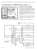
Страница 16: ...applicable local codes standards 2 Connect the burner following Figures 13 and 14 and any special instructions or wiring diagrams provided with the appliance burner or other components 3 The burner re...

Страница 17: ...ns or wiring diagrams provided with the appliance burner or other components 3 The burner requires a 120 VAC 60 hz single phase control power supply with a 5 amp fuse The control circuit current draw...

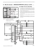
Страница 18: ...cycle to low fire as demand decreases This keeps the burner on longer reducing cyclic losses 2 The appliance must be equipped with a high fire control This would be a make on fall control either temp...

Страница 19: ...high low cycles The firing cycle can be much longer using low high low firing because the burner can cycle to low fire as demand decreases This keeps the burner on longer reducing cyclic losses 2 The...

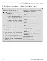
Страница 20: ...vent system Are voltages correct Burner appliance and motor correctly wired per burner and appliance manuals and wiring diagrams Gas manifold spud orifices on gas manifold item 29 page 5 sealed with p...

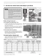
Страница 21: ...est instruments and make final burner adjustments Figure 17 Set initial low fire air damper setting Figure 16 Set initial combustion head position Low fire input High fire input Combustion head positi...

Страница 22: ...Failure to properly adjust the burner can result in severe personal injury death or substantial property damage Start the burner firing on oil Do not start the burner if the combustion chamber contai...

Страница 23: ...7 Restart the burner and check modulation again Continue with 1 through 6 above as needed until results are acceptable 8 Turn off the burner when Step 3 is completed before proceeding with setup for g...

Страница 24: ...o OFF The burner will shut down 5 Temporarily install two U tube manometer connections to check gas pres sures Install connections at the inlet pressure tap of the main manual gas valve and at the dow...

Страница 25: ...Tighten the swivel joint in place 10 Raise the damper motor linkage by pulling up on the damper linkage locknut and hold in this position The butterfly valve shaft slot must be horizontal If not use a...

Страница 26: ...xhausted from building If the building contains any exhaust fans or conditions that could affect vent performance check burner appliance vent operation with exhaust fans or other conditions operating...

Страница 27: ...tears can break away and plug the nozzle or fuel unit Perform the complete checkout procedures of pages 18 to 23 including system inspection and checks Inform the user of any problems found 8 Maintena...

Страница 28: ...h Oil nozzle size pattern Manifold gas pressure IWC High fire Low fire Inlet gas pressure IWC CO2 Oil Low Fire ______ Oil High Fire ______ Gas Low Fire ______ Gas High Fire ______ O2 Oil Low Fire Oil...

Страница 29: ...Model 702G O Advanced gas oil burners Instruction manual Carlin part number MN702GO Rev 06 23 14 29 Where appliance instructions differ from this manual follow the appliance instructions...

Страница 30: ...appliance instructions differ from this manual follow the appliance instructions 9 Dimensions Figure 19 Dimensional data straight gas train configuration 1 Honeywell R7897C primary control standard 2...

Страница 31: ...liance instructions differ from this manual follow the appliance instructions Figure 20 Dimensional data angled gas train configuration 9 Dimensions continued 1 Honeywell R7897C primary control standa...

Страница 32: ...ed for high fire 23556S 6 Fuel line 75291 7 Airflow switch 98522 8 Honeywell M436 damper motor 35808 9 Gasket 40246 10 14 airtube with pressurized flange 1 main gas inlet 1 2 pilot inlet 99541 11 14 c...

Страница 33: ...art number MN702GO Rev 06 23 14 33 Where appliance instructions differ from this manual follow the appliance instructions 10 Repair parts continued For parts not shown or listed contact factory and or...

Страница 34: ...ruct the flow of combustion and ventilating air Most motors currently used on residential type burners use permanently lubricated bearings and do not require field lubri cation Read the label on the m...

Отзывы: