51
14. Setting Control Surfaces.
All pushrods must move freely, without binding; adjust il required for
smooth operation. When selling control travel, be cautious that no servo
is hooked to a control in a manner that prevents the servo wheel from
moving through its complete range of rotation. For example, if the throttle
servo "buzzes" when moved to "full-throttle" position, the servo still has
movement left, but is jammed against the engine's full-throttle limit posi-
tion. This can damage the servo and drain the battery, leading to loss of
control, and a crash.
Move throttle lever on Tx to cycle the throttle from idle
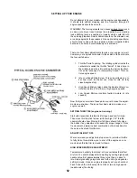
The following instructions describe how to set the control surfaces meas-
uring up and down movement using the angle templates provided. For
first flights, it is recommended that you set controls per the angle tem-
plates for "softer" control response. Later, after you are more familiar with
the airplane, you can always increase the throws as you prefer.
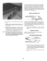
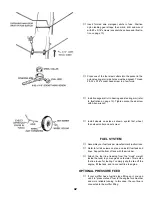
With elevator trim tab on Tx set in center, adjust elevator Mint-
Snap until elevator TE. is centered with stab as shown.
Move the elevator stick on Tx full up and down. The elevator
should move to match template angles, up and down.
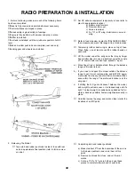
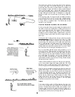
With rudder trim tab on Tx set in center, adjust Mini-Snap until
rudder TE. is centered with fin. Nose wheel should point straight
ahead.
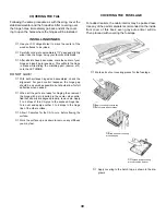
Move the rudder stick on Tx full right and left. The rudder should
move to match the rudder template angle, left & right. The nose-
wheel should move only very slightly as it doesn't take much to
steer on the ground.
With aileron trim tab on Tx set in center, adjust and connect
mini-snaps until ailerons are neutral with wing. Move the aileron
stick full right and left. The ailerons should move respectively up
and down to match aileron template.
THIS COMPLETES THE RADIO INSTALLATION
PILOT INSTALLATION
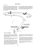
By special arrangement with Williams Brothers, a pilot figure
is included with your kit. When installed, it adds a final touch
of realism. The next few steps show how to assemble and
mount this pilot in your model. Also, the pilot platform holds
the battery and receiver in place.
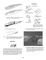
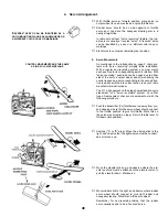
1.
Cut 1/4" off one end of one 1/8" ply pilot platform support (PPS).
Then glue two of them together as shown.
Drill 1/16" diameter holes through pilot platform and PS at
marked locations.
Using a #2 x 5/16" sheet metal screw, join platform to support.
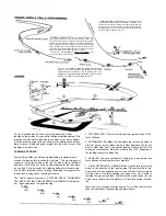
2.
Fit platform assembly inside cabin, engaging platform front with
notches in sides of former B, Adjust platform rear so it is about
horizontal. Carefully sand off end of PS if necessary for good fit
Glue PS firmly to fuse sides. Parts may be painted to match
fuse interior.
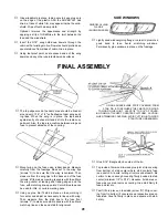
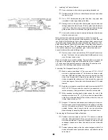
3.
Cut pilot halves apart at bottom, and trim off scrap. Rub each
half gently over fine sandpaper to smooth edges for joining.
Carefully align front and back and hold together with tape. Apply
dabs of glue at joint, remove tapes and complete gluing.
4.
Paint pilot figure as desired, flesh, hair and jacket colors are
your choice. Artist's acrylics and modeler's enamel paints are
available in many colors — no mixing required. Warning: do not
use lacquer based paints — they will destroy the plastic. When
painting face, leave eyes white, then later carefully add eye
details with a fine brush or toothpick. When dry, glue pilot in
place on platform.
CUT GAUGES FROM PLAN
Содержание Eagle 2
Страница 28: ...27 ...


