49
8.
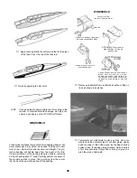
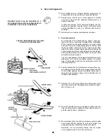
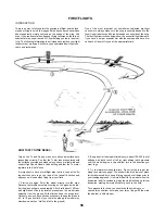
Installing The Throttle Pushrod.
Screw mini-snap on the extra-long remaining threaded rod.
Carefully bend rod to fit curve of throttle pushrod as shown in fuse
top view on plan.
Cut a 10½" throttle pushrod guide tube from long nylon tube
(remainder is steering pushrod guide tube).
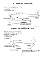
Starting at hole in firewall, slide throttle guide tube into fuse and
through upper side slot in former B, Nylon guide tube should pro-
trude 1/8" out firewall as shown in sketch below, Slide rod through
guide tube and connect mini-snap to engine throttle arm.
At rear end, make sure bend in wire leads it towards throttle servo
wheel as shown on plan.
Move pushrod back and forth to simulate servo action. The pushrod
should move freely; if not, adjust wire where necessary. Feel the front and
rear "limits" of the throttle arm. Later, when setting controls, be sure to set
the throttle servo linkage within the range of throttle arm movement, Glue
guide tube to firewall, former B and fuse side. If the guide tube needs sup-
port, make a "stand-off" from 1/4" scrap balsa (see plan), Tailor the stand-
off to suit the curvature of your installation, glue it only as required so it
doesn't interfere with pushrod sliding action.
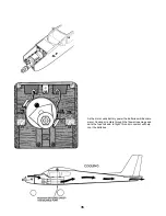
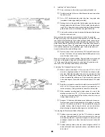
Remove servo wheel, and install the CG Pushrod Connector as
shown. This device lets you easily adjust throttle pushrod move-
ment. Remount servo wheel.
Make sure throttle servo is at idle position. Engine throttle arm also should
be at rear or idle position. Align and cut the pushrod wire so it extends
1/4" to the rear of the pushrod connector, and attach. Check action with
radio, and if OK, throttle pushrod hookup is completed.
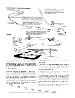
9. Installing The Nosegear Steering Pushrod.
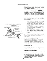
Make a square bend down 1/4" from one end of 1/16" x 16-3/4"
wire, and a slight upward bend 1" further back as shown on plan
side view. Slide steering guide tube over wire, and insert unbent
end of wire through hole in firewall, lower side slot in former B,
and back towards the rudder servo. Slip bent end into outermost
hole in steering arm. Guide tube should remain about 3/4" behind
firewall.
Bend the wire towards proper hole in rudder servo wheel but DO
NOT CUT YET! Move pushrod to check for free movement; cor-
rect as necessary. Glue guide tube to former B and fuse side.
With nosewheel pointing dead straight ahead, the end of the
steering arm should be 1/4" - 5/16" away from the firewall. Back
at the servo, allow additional 3/8" past servo wheel hole, and cut
it there. Bend cut end up 1/4".
Roughen 1/4" bent end with sandpaper for better grip of snap-nut.
Remove servo wheel to insert pushrod, add snap-nut, and then
remount. Check action with radio. This completes the nosegear
pushrod hookup, Later, during taxi tests, you can adjust nose
wheel steering by loosening steering arm socket head screw.
10a. Hooking Up Elevator and Rudder Pushrods.
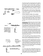
Position elevator pushrod so that the T.E. elevator is centered
with stab, Allow additional 5/16" past servo wheel hole, then cut
and bend forward end of pushrod, Roughen bend-up wire with
sandpaper, remove servo wheel and insert wire, and retain with
snap-nut.
Position rudder pushrod so that the rudder is aligned with fin. Cut
and bend forward end of pushrod as above, and attach to rudder
servo wheel.
Содержание Eagle 2
Страница 28: ...27 ...

