background image

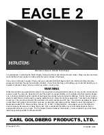
EAGLE 2

INSTRUCTIONS

Welcome to the sport of Radio Control flying!

Congratulations on selecting the Mark II Eagle--today’s top trainer and all around sport model.  Many new improvements
make the Mark II even easier to build and fly than past versions of the Eagle.

It may seem a bit early to speak of flying, but your successful first flight begins right here.  Before starting assembly,
please read carefully through this instruction booklet.  It won’t take that long, and building your model and installing your
equipment will seem easier, since you will know where you are going.

WARNING

While this aircraft is an excellent first choice for novice pilots, a radio-controlled model is not a toy and is not intended for
persons under 16 years old.  Keep this kit out of the reach of younger children, as it contains parts that could be danger-
ous.  A radio-controlled model is capable of causing serious bodily injury and property damage.  It is the buyer’s respon-
sibility to build this kit correctly and to properly install the motor, radio, and all other equipment.  Test and fly the finished
model only in the presence and with the assistance of another experienced R/C flyer.  the model must always be operat-
ed and flown using great care and common sense, as well as in accordance with the Safety Code of the Academy of
Model Aeronautics (5151 Memorial Drive, Muncie, IN 47302), 1-800-435-9262).  We suggest you join the AMA and
become properly insured prior to flying this model.  Also, consult with the AMA or your local hobby dealer to find an
experienced instructor in your area.  Per the Federal Communications Commission, you are required to use only those
radio frequencies specified “for Model Aircraft”.

CARL GOLDBERG PRODUCTS, LTD.

PT #2036 10/02

©Copyright 1978

Содержание Eagle 2

Страница 1: ...of younger children as it contains parts that could be danger ous A radio controlled model is capable of causing serious bodily injury and property damage It is the buyer s respon sibility to build this kit correctly and to properly install the motor radio and all other equipment Test and fly the finished model only in the presence and with the assistance of another experienced R C flyer the model...

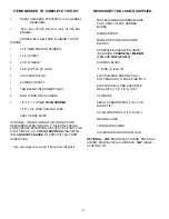
Страница 2: ... PLUG WRENCH CGP HINGE SLOTTING KIT 1 ITEMS NEEDED TO COMPLETE THIS KIT 1 RADIO GUIDANCE SYSTEMS 3 to 4 CHANNEL REQUIRED 1 29 to 45 2 CYCLE OR 40 to 60 4 CYCLE R C ENGINE PROPELLER FUEL TANK TUBING TO SUIT ENGINE 1 2 1 4 CGP SNAP ON SPINNER 1 2 1 4 WHEEL 2 2 1 2 WHEELS 1 2 OZ BOTTLE CA GLUE 1 CA ACCELERATOR 1 20 MINUTE EPOXY 1 TUB BALSA TINTED CGP FILLER 2 ROLLS IRON ON COVERING 1 1 2 x 8 x 12 CGP...

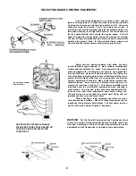
Страница 3: ... worn out dry cell batteries will be much greater than the higher initial cost of a re chargeable ni cad radio system something to consider Many of the radio systems now available feature servo reversing switches which allow you to reverse the response of the servo This feature simplifies radio installation and is a worthwhile consideration when selecting a radio system You may find radios with mo...

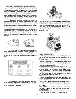
Страница 4: ...ing to the manufacturer s instructions As with other precision equipment a new engine should be broken in to enhance performance and extend its life Breaking in usually consists of running the engine with a rich fuel mixture and at lower RPMs until all the moving parts get to know each other better This can be done with the engine mounted in the model or securely clamped into a CGM Engine Test Sta...

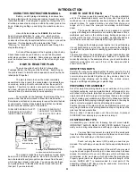
Страница 5: ... are working on with waxed paper The paper the plan is printed on can expand or contract slightly with changes in temperature or humidity Because of this a preformed part such as the notched wing trailing edge may not exactly match the plan This is no problem as slight deviations in the outline or size will not noticeably affect flight performance Because the fuselage plugs together and is self al...

Страница 6: ... If you don t see a slight fillet the CA has soaked into the wood edges and a second coat is needed SUPER JET sets up a bit slower with plywood and hardwood so hold such parts together a little longer than you would for balsa Comer fil lets take even longer to dry because there is not a thin layer The tendency is for all CA glues to set slower on harder woods or when in a thick layer Corner fillet...

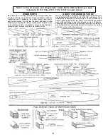
Страница 7: ...sired Save scrap until the model is completed in case a part is missing or damaged Also scrap is used in some building steps ABOUT THE WOOD IN THE KIT We strive to supply good quality materials in your kit Wood parts are inspected with regard to the function they will serve If an imperfection is spotted in a scrap comer of a die cut sheet and doesn t affect actual parts the sheet is considered acc...

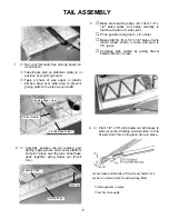
Страница 8: ... board on work bench Tape Eagle plan so stabilizer stab is in position over pinning board Tape a sheet of wax paper or plastic kitchen wrap over stab area to prevent gluing parts to the plan as you build 2 Carefully position die cut leading and trailing edge joiners and center platform and pin in place over the plan Glue these parts together using Super Jet Thick C A 4 From 1 8 x 1 4 strip balsa c...

Страница 9: ...e fin in the same manner as stab Let dry 8 Mark hinge locations on fin and rudder 9 Using the CG Center Line Marker provided mark center lines along edges of parts as shown Tilt marker so guide pegs touch the wood then lightly pass the marker back and forth Point will scribe center line 6 Transfer hinge locations from plan toT E Cut elevator at marks to match stabilizer tips ...

Страница 10: ... will hold the hinge in place while sliding the matching part aileron etc onto the JET HINGE DO NOT GLUE With both surfaces hinged and assembled check the alignment For good control response the hinge gap should be as small as possible but should allow for full deflection when needed Remove the hinges and complete the construction of the airplane Note in the next few steps the hinges will be TEMPO...

Страница 11: ...dle and narrow strip again keeping things square ASSEMBLING DIE CUT BEVELING TOOLS FROM 1 8 PLY 15 Tape T E of elevator and rudder to work surface Using appropriate beveling tool sand LE to center line Turn parts over and repeat beveling for other side 14b Cut two strips of 100 200 grit sandpaper to size shown above Tack cement sand paper to tools THIS COMPLETES THE TAIL ASSEMBLY CONSTRUCTION ...

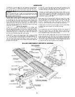
Страница 12: ...ileron inboard section Note from Step 4 on in the wing assembly photos sketches the A B wing is shown ailerons not glued to T E but the wing assembly procedure is the same for the C wing The Ailerons the movable control surfaces at the trailing edge of the A or B wing allow more precise control of maneuvers The A wing has average dihedral the upward bend of the wings and is quite stable and maneuv...

Страница 13: ...ctly don t worry this is due to expansion and shrinkage of the plan paper Do not glue rib No 2 at this time Glue ribs No 4 to T E and spar Glue 1 8 x 7 16 x 3 9 16 ply T E brace to T E as shown Note four 3 9 16 pieces are provided two are T E braces the other two are later used as servo mounting rails Do not glue rib no 2 at this time 4 Position rib 3 in place over plan and glue it to T E brace an...

Страница 14: ... sheet from wing and using metal straight edge cut a One across sheet at spar marks Replace sheet in wing trim slightly if required until it fits well 6 Position one rear bottom sheet at rear of spar Place other rear bottom sheet at T E so it overlaps the first one Holding both sheets in place trim first sheet even with edge of second sheet 7 Glue L E sheeting to L E and spar Glue two rear sheetin...

Страница 15: ...par T E only Hold each rib up straight as it dries 11 Three set back gauges are supplied one for A one for B and one for C wing Position proper gauge touching bottom spar Touch end of top spar to gauge and set spar in rib slots Glue top spar to all ribs Glue wing tip gussets to L E and T E 12 Working a few ribs at a time apply SUPER JET to glue loose ribs to L E Gently squeeze LE into ribs and hol...

Страница 16: ...t If the fit between most parts is a little loose because one part protrudes too much slightly sand only the protrud ing part for better fit When sanding it is better to take off too little than too much TEMPORARILY set dihedral joiners in place on each side of spars using die cut clamps provided to hold join ers tight against spars Be sure RIGHT WING is held firmly against LEFT WING and pin in pl...

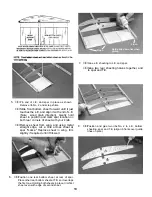
Страница 17: ...with centerline of wing Adjust rib to align with spar center joint T E bottom sheeting and L E joints Glue in place Glue remaining halves of second No 1 rib to first rib making double thickness center rib at center joint Be sure to glue any joints in the wing still needing glue 20 Remove all clamps etc Try top sheeting in place trimming to fit as required Match edge of sheeting with center of rib ...

Страница 18: ...ip aileron wires they allow the threaded end horn of the wire to rotate forward and back 23b Using NO GLUE AT FIRST temporarily slide bearing tabs in wing slots and position both T E inboard sec tions over aileron wires Check for horn movement top to move about 3 4 total fore and aft Remove TE inboard sections and glue bearing tabs into wing Carefully glue TE inboard sections in place CAUTION Keep...

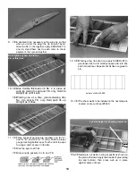
Страница 19: ... a piece of matchbook cover about 1 32 at both ends Place TE on plan and mark hinge locations three hinges per wing half Transfer hinge locations to ailerons 26 Temporarily fit ailerons in wing with hinges checking for hinge alignment 27 Using beveling tool EA bevel front edge of aileron to centerline Turn aileron ever and repeat sanding Repeat for other aileron ...

Страница 20: ...as shown on page 39 If they bind at T E try gently forcing them on or sand a slight recess for them in T E 29 Using 240 grit fine sandpaper flat sand entire wing to blend surfaces and remove high spots Cut 1 x 6 half hard aluminum sheet into 3 pieces Lightly sand aluminum surfaces for better gluing Apply a bead of SUPER JET to half of a 3 aluminum sheet and glue it to wing T E as shown When dry ap...

Страница 21: ...ily mount servo in die cut mounting tray See fuse side view on plan for added details of aileron servo installation 35 Carefully position servo 1 2 behind bottom spar and mark size for opening THE SERVO RAILS SHOWN IN THESE PHOTOS HAVE BEEN REPLACED WITH THE PLY MOUNTING TRAY STEP 34 Cut out bottom sheeting Remove material from rib No 1 as required to suit your servo Glue servo tray to wing and fi...

Страница 22: ...walls and tape opposite edge together Squeeze firewalls together using die cut clamps When dry remove clamps and tapes set clamps aside for use later 3a Repeat firewall joining procedure and make doubled Former B 3b From 1 8 x1 2 x18 balsa cut and glue strips to match formers as shown Apply strips as shown Note Former C strip at bottom only 4 Be sure sides are laid down left right as shown Tempora...

Страница 23: ...t Drill four 1 8 diameter holes through firewall at four lower punch marks Study engine above most engines have throttle arm on the side shown and require two more 1 8 holes to be drilled as indicated for throttle and steer ing pushrods If your throttle arm is on the opposite side use the opposite locations shown with an X SMALL TRIANGLE SHAPED PIECES SHOWN ABOVE HAVE BEEN ELIMiNATED FROM THE KIT ...

Страница 24: ...nd Spread fuse fronts apart and plug former B into holes in body sides Hold parts together with a rubber band Carefully spread fuse rear open and plug former F in place and hold with a rubber band Remove tape from tail end 8b Install firewall remaining formers C D and E in same manner using rubber bands to hold parts 8d Lock tabs at both ends of top sheet into corre sponding notches in fuse sides ...

Страница 25: ...ue windshield top former and dashboard solidly in place 12 Tape hatch cover and dashboard fop together as they fit from die cut sheet 10 When satisfied with alignment permanently glue sides formers and sheet parts in place Apply a bead of SUPER JET along all joints inside and outside or from both sides in the case of farmers it will penetrate the joint and leave a slight reinforcing fillet ...

Страница 26: ...4 Remove hatch cover from fuse Refer to plan for correct placement of ply tongue then glue tongue to hatch cover Try in place Glue dashboard top to hatch supports and dashboard 15 Place the landing gear L G mount on inside bottom of fuse The cutouts at each end of mount must be posi tioned evenly over the slot in the fuse bottom Glue mount in place 16 The L G braces interlock with L G mount Glue b...

Страница 27: ...be to a pilot sitting in the cabin 3 Position engine on breakaway so there is approximate ly 1 8 between fuse front and spinner back or propeller if spinner isn t used 3a Notice the engine in the top view on the plan is angled slightly to the right This RIGHT THRUST although small is important View your model from above and carefully measure dis tance from tail end to one propeller tip propeller m...

Страница 28: ...27 ...
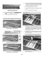
Страница 29: ...engine mounting hole locations place scrap ply under parts when drilling to avoid splintering 5 Permanently install four blindnuts in bottom of break away using socket head screws and washers to pull blindnuts up into the screw holes as shown Remove screws after seating blindnuts 6a On die cut lines mark cross lines about 1 4 ahead of and 1 4 behind holes as shown ...

Страница 30: ... position Remove hatch cover and apply SUPER JET to hold down Replace hatch on fuse gluing it to hold down Let dry Secure hold down to hatch with two 2 x 3 16 screws Set hatch in position on fuse Mark location as shown for 2 shoulder screw Install screw in marked location exposing enough unthreaded shank to engage hold down Snap on and off several times 9 Carefully remove side windows from vac for...

Страница 31: ...otch Watch grain and very careful ly trim it off Smooth this edge with a few light passes of the sanding block 10c Trial fit fin in place Glue dorsal fin to main fin but not to fuse as shown Finish sanding 11 Flat sand fuse and round off corners except in the fol lowing areas top of cabin top of tail mounting area and window openings repeat do not sand these areas except very lightly to remove bur...

Страница 32: ...file a slight recess 1 long at one end of each 5 16 square x 24 balsa push rod Drill a 1 16 diameter hole 1 4 deep at end of recess in both pushrods Glue rods into balsa pushrods as shown When dry taper ends of pushrods and round off cor ners Bind with strong thread coat with glue and let dry The other end of the pushrods is completed later during radio installation THIS COMPLETES THE FUSELAGE ASS...

Страница 33: ...hardwood Fuselage Bolt Blocks Wing Procedure substitute the modifications below where applicable 1 For Bolt On wing there are only two part changes instead of the 5 64 die cut No 1 Ribs use the new 1 8 balsa No 1 ribs Balsa filler blocks must be glued inside the wing at the Trailing Edge The instructions will remind you when to add these parts 2 After wing is completely assembled cut a 1 4 wide op...

Страница 34: ...clearance for dowel 4 Position wing on fuselage and press T E down to rest on fuselage top Measure for equal distance from wing tips to rear end of model and adjust wing so it is setting square on fuselage Hold wing in place with tape Measure 2 from wing TE and 1 2 in from fuselage sides Drill two holes 13 64 diameter down through wing and fuselage mounting blocks Remove wing Enlarge WING HOLES ON...

Страница 35: ...strations The Astro Flite Cobalt 25 Geared Motor system as shown here is recommended IMPORTANT Read and follow the manufacturer s instructions regarding the installation and safe operation of each component of your electric motor system The motor batteries etc are very powerful and must be operated as recommended by the manufacturer Three 1200 MAH battery packs are required for power These bat ter...

Страница 36: ...35 As the motor uses battery power the batteries will become warm Cooling air enters through the firewall openings and exits the fuse tail end In flight this air movement will help cool the batteries ...

Страница 37: ...04 3 4 diameter tailwheel 1 16 dia x 6 wire for strut FLOATS make any large pond or lake your runway Water flying adds a new dimension to your flying fun CG Super Floats are recommended because they are easy to build and perform well Floats can be added at a later time with little modification to your model Superfloats CG 296 Two 5 32 dia x 36 wires for struts Finishing materials see float instruc...

Страница 38: ...with 000 steel wool Mask the design with vinyl tape NOTE Before starting it s a good idea to do s lay out of the covering pieces you will need to cut from the covering rolls so that you make efficient use of your material You can draw patterns on UltraCote s paper backing Be sure to leave a little extra material so you can go around the edge of the section you are covering COVERING THE WING Before...

Страница 39: ...ut the design as you go Larger designs such as sunbursts should be positioned and the widest end tacked down first Then working towards the narrow end iron the design down INSTALLING WING TIPS For better bonding of plastic wing tips use a pin to make a series of many punctures through the UltraCote into the top and bottom edges of the tip ribs In addition light ly sand the inside edges of the plas...

Страница 40: ...ll as possible but should allow for full deflection when needed When all the parts are ready for hinging then remount the hinge with a pin inserted in the center when satis fied that all parts are aligned properly remove pin Apply 3 to 4 drops of thin CA glue to the exposed hinge line Turn over and apply another 3 to 4 drops to the hinge line of the other surface Allow 10 minutes for the CA to cur...

Страница 41: ...decal on the model and stick in place Then working from the center rub the decal down while peeling off the backing CAUTION FOLLOW INSTRUCTIONS CAREFULLY FLASHING 1 CAREFULLY REMOVE FLASHING AT BOTTOM OF WINDSHIELD SIDES 2 TRIM SCRAP FROM FRONT OF WINDSHIELD BY CUTTING ON MARKED LINE 3 MAKE TWO VERTICAL CUTS AT MARKED LINES 4 OPEN SACK SLIGHTLY INSERT SCISSOR BLADE HALF WAY AND CUT ON LINE REMOVE ...

Страница 42: ...out to the wing tips arrows A to be sure that the wing is centered Then measure from the wing tips to the back end of the fuse arrows B to make sure wing is square with fuse Mark the wing center at leading and trailing edges and the fuse with matching line up points Color Stripe tape can be used for this or certain marking pens Using no glue trial fit stab in place on fuse marking it for center an...

Страница 43: ...les as shown eyelet first wheel then wheel collar and set screw FUEL SYSTEM Assemble your fuel tank per manufacturer s instructions Refer to full size views on plan and install fuel tank and lines Support bottom of tank with foam rubber Attach the fuel line leading from the clunk weight inside the tank to your engine s carburetor This is also the line to use for fueling You simply slip the line of...

Страница 44: ...them with grommet shock mounts in servo trays which are in turn shock mounted Keep them clean If a neutral position should drift it is a sign of a change find out WHY before flying again TRANSMITTERS Keep your transmitter clean and free from fuel residue and dirt Battery condition and RF output should be monitored and the system should be aligned and tuned annual ly Do not transport under vibratio...

Страница 45: ...ng in place on top of fuse When flying use at least seven 64 rubber bands on each side Lift the model under the wing near the fuse by finger tips A better way is to use a simple set up with a couple of 1 4 dowels with rounded tops spaced 5 apart a Move finger tips or balance stand through the balance range until model is level b If you need to support the model outside the balance range to get it ...

Страница 46: ...rious controls FOR A or B WING With Ailerons USED WITH C WING ONLY Non Aileron THE INSTALLATION ILLUSTRATED HERE IS A GUIDE DEPENDING ON YOUR ENGINE AND R C GEAR YOU MAY NOT BE ABLE TO FOLLOW IT EXACTLY READ THE INSTRUCTIONS THAT CAME WITH YOUR RADIO THOROUGHLY BEFORE STARTING RADIO INSTALLATION Apply tape which you can write on to each servo Identify each servo for its control function Mark the p...

Страница 47: ...e of the servo s output wheel and after checking the control response a servo responding in the wrong direc tion is easily switched to correct action see your radio manufacturers instructions The 2 1 arrangement on the plan shows standard servo placement for a servo reversible system For either type of radio system check your equipment out with the following procedure Push the transmitter Tx throt...

Страница 48: ...red Working from cabin feed rudder pushrod threaded end through fuse rear and out exit hole Use a loop of string or wire to pull threaded end up through exit hole Twist mini snap clevis onto threaded rod Hold pushrod wire with pliers while installing mini snap Connect to rudder horn ELEVATOR HORN Large Insert threaded end of elevator pushrod from cabin through fuse rear and out slot opening about ...

Страница 49: ...n of the mounting screws Remove the servos With a 1 16 drill bit drill holes in tray Reinstall servos and gently fasten them in place with screws provided with your radio system or with 2 x 3 8 sheet metal screws Engage tab at rear of servo tray into matching side notches in former C Position 7 16 x 3 9 16 ply mounting rail under front of servo tray so rail is about 1 1 2 above fuse floor If the r...

Страница 50: ...4 to the rear of the pushrod connector and attach Check action with radio and if OK throttle pushrod hookup is completed 9 Installing The Nosegear Steering Pushrod Make a square bend down 1 4 from one end of 1 16 x 16 3 4 wire and a slight upward bend 1 further back as shown on plan side view Slide steering guide tube over wire and insert unbent end of wire through hole in firewall lower side slot...

Страница 51: ...or tape to hold the foam around the battery It is also good to place battery and Rx in individual plastic bags to protect against fuel and oil Position battery in fuse and hold in place with additional foam rubber 13 Receiver Rx Do not cut the antenna wire attached to the Rx Wrap Rx carefully in foam like the battery Re connect all cables so R C system is operational be sure that each servo is plu...

Страница 52: ...ound With aileron trim tab on Tx set in center adjust and connect mini snaps until ailerons are neutral with wing Move the aileron stick full right and left The ailerons should move respectively up and down to match aileron template THIS COMPLETES THE RADIO INSTALLATION PILOT INSTALLATION By special arrangement with Williams Brothers a pilot figure is included with your kit When installed it adds ...

Страница 53: ...gine stop 3 High Speed Mixture also called the Needle Valve con trols the mixture of fuel air at high engine speeds 4 Low Speed Mixture controls fuel air mixture at Idle speeds Now that you know where these parts are let s make the adjust ments one at a time There are four basic steps to make your engine run well SETTING THROTTLE engine not running Start with transmitter throttle stick full open a...

Страница 54: ...justment should be a bit on the lean side to give the best transition Once set it may never be adjusted again If engine will not run at idle open throttle up to 1 3rd and try to determine if it s rich sputtering or lean dies quickly and adjust slow speed screw Then slow engine lower and re adjust if nec essary A good sport 2 cycle should idle 2 500 RPM easily Some engines will go to 2 000 but that...

Страница 55: ...ting an R C device which could affect your receiver and cause your plane to crash LEARNING TO FLY Your chances of success are enormously increased if you have an instructor Learning to fly is harder than it looks and a mistake can seriously damage or destroy your model Even full scale pilots have problems learning to fly models because it s different they re not in the cockpit It s worth real effo...

Страница 56: ... is not pointing straight ahead and should be adjusted until i1 is correct Adjust the nose wheel only loosening the steering arm to do so Do a lot of practicing with the mode coming towards you as it often will in the sky When the plane is pointing at you the steer ing will appear reversed When you give right rudder the plane turns to your left but the model actually is turning to its right as you...

Страница 57: ...to have a total flight plan in mind Look at the fly ing sketches here to get an idea of the take off direction and space you will need when flying from your field 1 Start your engine Point the model directly into the wind Advance the throttle smoothly steering on the ground with rud der the plane will gain speed rapidly After it rolls about 100 feet add slight back stick up elevator pressure so th...

Страница 58: ...a gentle turn to point the model in the direction of the landing area Reduce throttle to idle Keep nose of plane slightly down so you don t stall Steer the plane into the wind as it glides keeping the wings level Let it settle in towards the ground and land Just before the model lands you can add a touch of back stick up elevator to flare and soften the land ing Walk over to your plane stop the en...

Страница 59: ...d pushrod guide tubes included a black cockpit insert and put in wing guide tubes for quick easy installation of aileron servo wires Both versions include a complete hardware package and our fully illustrated step by step instruction booklet will have you out at the field in record time Get a Tiger now at your local hobby retailer and you ll have it jumping through hoops in no time The Tiger 2 Tig...

Отзывы: