pCOWeb
+030220966 – rel. 1.1 – 12.12.2017
8
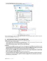
1.2
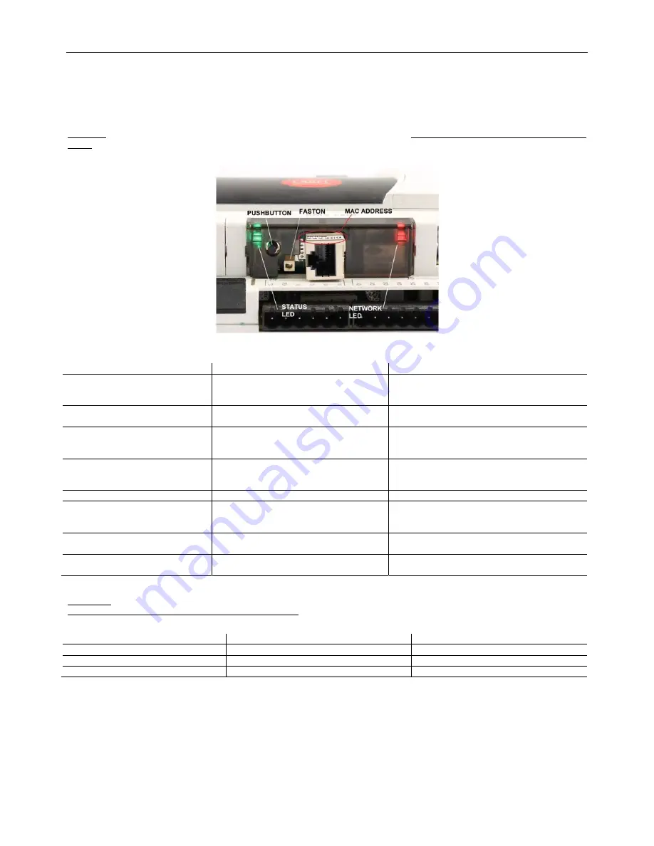
USER INTERFACE: BUTTON and LEDs
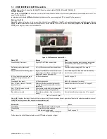
pCOWeb
features (
Figure
1.b
) a button (PUSHBUTTON) and two indicator lights (STATUS LED and NETWORK LED).
Functions of the button
When starting up the
pCOWeb
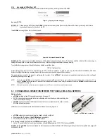
, this is used to select, for network communication, whether to use the factory parameters or the user parameters (see 3.1.2 on
page 12 for the procedure);
In normal operation, reboots
pCOWeb
without needing to disconnect the power supply (see 9.10.1 on page 53 for the procedure).
Meaning of the LEDs
Status LED: displays information on the communication status between
pCOWeb
and the
pCO
, and must normally be green and flash around 3 times a
second; in special circumstances it displays the operation of service activities, such as the restart of the internal program on the
pCOWeb
, the remote
updating of the program, or others. See the table below.
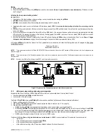
Figure 1.b - MAC address and indicator LEDs
Status LED
Meaning
Notes
Green flashing (3 times/sec)
Regular
pCO
-
pCOWeb
communication
When running demanding tasks (sending a large number
of notifications), this may be green steady for a few
seconds
Red flashing slowly (once every 2
seconds)
pCO
-
pCOWeb
communication not established
Check the settings in paragraph 9.5 on page 46
Single red flash and then flashing green
Single
pCO
-
pCOWeb
communication error
,
one
failed response from the
pCO
or attempt to write a
variable with an index higher than 207
After 5 failed responses, the Status LED starts flashing
red until communication resumes
[Off, then] green-red repeated in rapid
succession, then green steady for 1
minute
pCOWeb
reboot phase
See 9.10 on page 53
Green steady for a minute
pCOWeb
reboot phase
Wait for the conclusion of the reboot
Red – Off slow (1 second – 1 second)
repeated 3 times
Detection of button pressed during reboot for
selecting factory parameters (rather than User
parameters)
Release the button to confirm, see 3.1.2 on page 12
Red – Off fast (3 times a second)
repeated 3 times
During reboot, confirms that factory parameters
have been selected by pressing the button
See 3.1.2 on page 12
Blue steady for a minute
During firmware update, writing to non-volatile
memory
Do not interrupt the power supply, see 9.11 on page 54
Table 1.a - Status LED signals
Network LED: displays the status of the physical network connection (Ethernet connection signals), regardless of whether the network parameters are correct;
usually this must be green and flash when data is transmitted/received.
Table 1.b - Network LED signals
For the connection to the Ethernet network, use an S/FTP cable, category 5e or higher
Network LED
Meaning
Notes
Green steady
Correct Ethernet data connection signals
-
Green flashing
Correct Ethernet data exchange
-
Red
No Ethernet signal detected
See 0 on page 13


