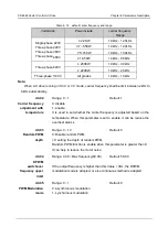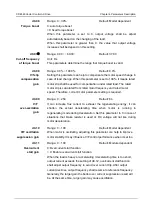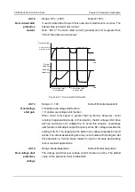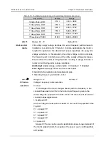
CDE360 Vector Control AC Drive Chapter 6 Parameters Description
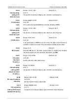
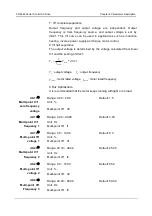
C5.07
①
Range:
C5.08
~8.00
Default: 6.70
Unit: V
AI high level
threshold
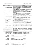
This defines the threshold voltage that AI treated as high level should be
greater than.
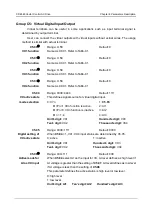
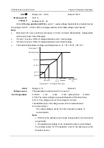
C5.08
①
Range: 1.00~
C5.07
Default: 3.20
Unit: V
AI low level
threshold
This defines the threshold voltage that AI treated as low level should be
less than.
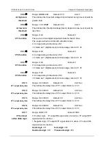
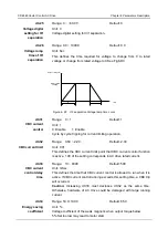
C5.09
①
Range: 0~45
Default: 0
VY1 function
There are 4 virtual digital output terminals for the AC drive.
The usage method is similar with actual terminal.
0: Corresponding to the status of X1
>0: Same as Y (digital output) terminal usage, refer to C1.01.
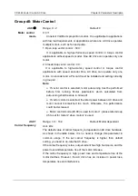
C5.10
①
Range: 0~45
Default: 0
VY2 function
0: Corresponding to the status of X2
>0: Same as Y (digital output) terminal usage, refer to C1.01.
C5.11
①
Range: 0~45
Default: 0
VY3 function
0: Corresponding to the status of X3
>0: Same as Y (digital output) terminal usage, refer to C1.01.
C5.12
①
Range: 0~45
Default: 0
VY4 function
0: Corresponding to the status of X4
>0: Same as Y (digital output) terminal usage, refer to C1.01.
C5.13
Range: 0.0~3600.0
Default: 0.0
Unit: Sec
VY1
output delay time
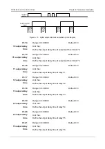
This defines the delay time of VY1 output. Refer to C1.13.
C5.14
Range: 0.0~3600.0
Default: 0.0
Unit: Sec
VY2
output delay time
This defines the delay time of VY2 output. Refer to C1.13.
C5.15
Range: 0.0~3600.0
Default: 0.0
Unit: Sec
VY3
output delay time
This defines the delay time of VY3 output. Refer to C1.13.
C5.16
Range: 0.0~3600.0
Default: 0.0
Unit: Sec
VY4
output delay time
This defines the delay time of VY4 output. Refer to C1.13.
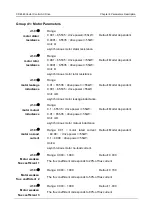
C5.17
Range: 0000~1111
Default: 0000
VY terminal
active state logic
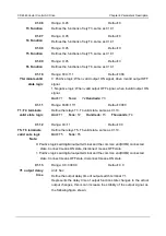
0: Positive logic. VY output ON signal when it is active. VY output OFF
signal when it is inactive.
1: Negative logic. VY output OFF signal when it is active. VY output ON
signal when it is inactive.
Unit's digit:
VY1
Ten's digit:
VY2
Hundred's digit:
VY3
Thousand's digit:
VY4

