Chapter 8
8-15
8.3.2 Toner Level Detection
0020-8176
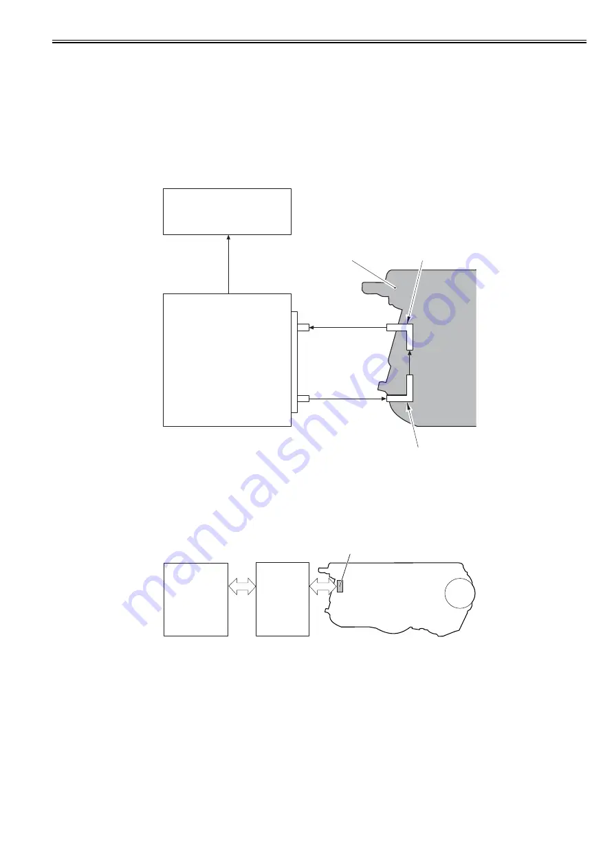
The machine uses a transparent toner level detection method.
With this method, light goes through the toner cartridge while the toner is stirred driven by the drum motor.
The DC controller detects the toner level by monitoring how long it takes for the light to go through the cartridge.
Explanation of operation
The DC controller illuminates the LED on the memory controller PCB.
The light emitted from the LED enters into the toner cartridge via the light-receiving light guide.
Since the stirred toner blocks the light, how long it takes for the light to go through the cartridge differs depending on the toner volume.
The light that went through the toner cartridge goes out from the light-sending light guide and is received at the memory controller PCB.
The toner level is detected based on the length of the time it took for the main controller to receive the light. The higher the toner level is, the shorter time is taken
to receive light. On the other hand, the lower the toner level is, the longer time is taken.
When the light-receiving time becomes longer than the specified value, the DC controller judges that the toner level is low and displays "Toner level is low" in the
control panel.
F-8-20
8.3.3 Memory Tag Control
0019-5024
The DC controller detects the use condition of the toner cartridge by reading/writing data saved in the memory tag.
When the machine is placed in the following condition, the DC controller determines that it is a communication error of the memory tag and notifies the main
controller of "Warning: cartridge memory abnormality".
- Access abnormality: When reading/writing failed
- Data abnormality: When a fault was found in the data which was read/written
F-8-21
8.3.4 Toner Cartridge Detection
0019-5025
The time required until the rotating drum motor stops varies depending on the presence/absence of the toner cartridge. When the toner cartridge is present, the load
applied to the drum motor increases, which shortens the stop time.
The DC controller detects the presence/absence of the toner cartridge based on the stop time of the drum motors (M6 to 9) after the initial drive of the drum motors
when the power is turned ON or the front cover is closed.
When it is determined that the toner cartridge is absent, the DC controller stops the machine's operation and displays "No toner cartridge" on the control panel.
Memory controller PCB
DC controller PCB
Light receiver
Light emitter (LED)
Light-receiving light guide
Light-sending light guide
Toner cartridge
T
oner le
v
e
l
signal
Memory tag
Toner cartridge
DC controller
PCB
Memory
controller
PCB
Содержание iR C1020 Series
Страница 1: ...Sep 8 2008 Service Manual iR C1020 Series iR C1021i ...
Страница 2: ......
Страница 6: ......
Страница 18: ...Contents ...
Страница 19: ...Chapter 1 Introduction ...
Страница 20: ......
Страница 22: ......
Страница 57: ...Chapter 2 Installation ...
Страница 58: ......
Страница 60: ......
Страница 73: ...Chapter 3 Basic Operation ...
Страница 74: ......
Страница 76: ......
Страница 81: ...Chapter 4 Main Controller ...
Страница 82: ......
Страница 84: ......
Страница 97: ...Chapter 5 Original Exposure System ...
Страница 98: ......
Страница 100: ......
Страница 112: ......
Страница 113: ...Chapter 6 Original Feeding System ...
Страница 114: ......
Страница 116: ......
Страница 132: ......
Страница 133: ...Chapter 7 Laser Exposure ...
Страница 134: ......
Страница 136: ......
Страница 143: ...Chapter 8 Image Formation ...
Страница 144: ......
Страница 146: ......
Страница 180: ......
Страница 181: ...Chapter 9 Pickup and Feed System ...
Страница 182: ......
Страница 213: ...Chapter 9 9 29 F 9 79 1 2 3 ...
Страница 214: ......
Страница 215: ...Chapter 10 Fixing System ...
Страница 216: ......
Страница 218: ......
Страница 233: ...Chapter 11 External and Controls ...
Страница 234: ......
Страница 263: ...Chapter 12 e maintenance imageWARE Remote ...
Страница 264: ......
Страница 266: ......
Страница 275: ...Chapter 12 12 9 F 12 27 ...
Страница 280: ......
Страница 281: ...Chapter 13 Maintenance and Inspection ...
Страница 282: ......
Страница 284: ......
Страница 286: ......
Страница 287: ...Chapter 14 Measurement and Adjustments ...
Страница 288: ......
Страница 290: ......
Страница 293: ...Chapter 15 Correcting Faulty Images ...
Страница 294: ......
Страница 296: ......
Страница 304: ...Chapter 15 15 8 15 3 2 2 Fans 0019 5064 F 15 11 T 15 3 Notation Name FM1 main unit fan FM2 duplex fan FM2 FM1 ...
Страница 313: ...Chapter 15 15 17 F 15 19 21 22 28 29 30 31 24 14 15 16 23 26 25 32 27 20 19 18 17 2 13 6 10 33 1 8 4 3 12 11 5 7 9 ...
Страница 317: ...Chapter 16 Error Code ...
Страница 318: ......
Страница 320: ......
Страница 331: ...Chapter 16 16 11 ...
Страница 332: ......
Страница 333: ...Chapter 17 Special Management Mode ...
Страница 334: ......
Страница 336: ......
Страница 343: ...Chapter 17 17 7 ...
Страница 344: ......
Страница 345: ...Chapter 18 Service Mode ...
Страница 346: ......
Страница 348: ......
Страница 388: ......
Страница 389: ...Chapter 19 Upgrading ...
Страница 390: ......
Страница 392: ......
Страница 396: ...Chapter 19 19 4 3 Click Next F 19 4 4 Select a USB connected device and click Next F 19 5 ...
Страница 397: ...Chapter 19 19 5 5 Click Start F 19 6 6 Click Yes F 19 7 Download will be started F 19 8 ...
Страница 399: ...Chapter 19 19 7 ...
Страница 400: ......
Страница 401: ...Chapter 20 Service Tools ...
Страница 402: ......
Страница 404: ......
Страница 407: ...Sep 8 2008 ...
Страница 408: ......


