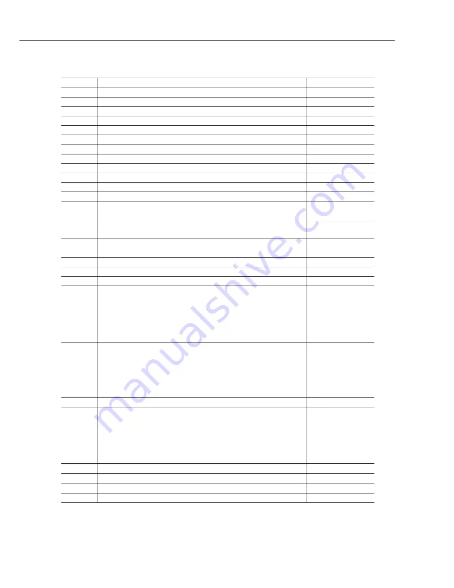
Canon imagePROGRAF W6200 Скачать руководство пользователя страница 89

b) Errors

Code*

1

Status

Maintenance No.*

2

E02000

No roll media

7.3.1

E0200A

Paper width not detected

7.3.3

E0200B

Media loading position error

7.3.3

E0200C

Media leading edge not detected

7.3.3

E0200D

Cut sheet trailing edge not detected

7.3.2

E0200E

Media is too small

7.3.3

E0200F

Media is too large

7.3.3

E02010

Media is skewed

7.3.3

E02015

Cutting failure

7.3.4

E02016

Paper became misaligned during printing

7.3.2

E02017

Media right edge not detected

7.3.3

E02018

Media left edge not detected

7.3.3

E02400

Cut sheets were loaded even though the received data 

7.3.5

indicated roll media

E02401

Roll media was not loaded even though the received data 

7.3.5

indicated roll media

E02402

Cut sheets were not loaded even though the received data 

7.3.5

indicated cut sheets

E02403

Media was too small during printing of adjustment pattern

7.3.5

E02404

Borderless printing was specified when cut dust reduction function is set to on

7.3.6

E02405

Invalid paper position for borderless printing

7.3.6

E02500

No ink (Bk)

7.3.7

E02501

No ink (Y)

E02502

No ink (M)

E02503

No ink (C)

E02504

No ink (PM)

E02505

No ink (PC)

E02506

Ink tank not installed (Bk)

7.3.8

E02507

Ink tank not installed (Y)

E02508

Ink tank not installed (M)

E02509

Ink tank not installed (C)

E0250A

Ink tank not installed (PM)

E0250B

Ink tank not installed (PC)

E02520

Displayed before printing when "Ink Check Off" menu is set to "Yes".

7.3.9

E02521

Remaining ink low (Bk)

7.3.10

E02522

Remaining ink low (Y)

E02523

Remaining ink low (M)

E02524

Remaining ink low (C)

E02525

Remaining ink low (PM)

E02526

Remaining ink low (PC)

E02800

No head

7.3.11

E02801

Head overheating

7.3.11

E02802

Incorrect head was installed

7.3.11

E02803

Head EEPROM error

7.3.11

*1: The codes correspond to the numbers shown on the display in the service mode.

Codes in parentheses are not shown on the display when error occurs.

*2: The maintenance numbers correspond to the section title numbers in 

Part 5: 7

TROUBLESHOOTING

.

Part 3: Operations

W6200

3-42

Содержание imagePROGRAF W6200

Страница 1: ...AY3 4308 002 OCT 2003 COPYRIGHT 2003 CANON INC CANON W6200 N 1003 0 00 0 PRINTED IN JAPAN IMPRIME AU JAPON REVISION 0 ...

Страница 2: ...1003 N 0 00 0 ...

Страница 3: ......

Страница 4: ...es not apply to any countries where such provisions are inconsistent with local law Trademarks The product names and company names appearing in this manual are the registere d trademarks or trademarks of the individual companies Copyright This manual is copyrighted and all rights reserved Under the copyright laws this manual may not be copied reproduced or translated into other languages in whole ...

Страница 5: ...Instructions This part explains how to operate the unit properly how it is installed and how to use the service mode Part 4 Technical Reference This part outlines the unit operation giving a technically Part 5 Maintenance This part explains maintenance of the unit It includes details of disassembly assembly adjustments required when assembling troubleshooting procedures and wiring circuit diagrams...

Страница 6: ... 3 4 Refilling the ink 1 12 3 PRECAUTIONS WHEN SERVICING THE PRINTER 1 12 3 1 Stored Data 1 13 3 2 Firmware Confirmation 1 13 3 3 Precautions Against Static Electricity 1 13 3 4 Precautions for Disassembly Assembly 1 13 3 5 Self Diagnostic Feature 1 13 3 6 Disposing of Waste Ink 1 13 3 7 Disposing of Lithium Battery Part 2 PRODUCT SPECIFICATIONS 2 1 1 PRODUCT OVERVIEW 2 1 1 1 Product Overview 2 2 ...

Страница 7: ... 1 1 Service mode operation 3 25 4 1 2 Map of the service mode 3 28 4 1 3 Details of service mode 3 39 4 2 Error Indicators 3 40 4 2 1 Overview of warning and error codes 3 41 4 2 2 Warning and error codes 3 44 4 2 3 Description of warning and error codes 3 50 5 PRINTER SPECIAL MODE 3 50 5 1 Controller Replace Mode 3 50 5 2 Download Mode 3 51 6 PRINTER SERVICE SOFTWARE 3 51 6 1 Overview of Service...

Страница 8: ...2 Structure of purge unit 4 31 3 6 Maintenance Cartridge 4 31 3 6 1 Maintenance cartridge 4 32 3 7 Air Flow 4 32 3 7 1 Air flow 4 33 3 8 Paper Path 4 33 3 8 1 Overview of paper path 4 37 3 9 Structure of Paper Path 4 37 3 9 1 Structure of feed rollers 4 38 3 9 2 Structure of cutter unit 4 39 4 PRINTER ELECTRICAL SYSTEM 4 39 4 1 Overview 4 41 4 2 System Controller 4 41 4 2 1 System controller compo...

Страница 9: ...ge unit 5 30 5 2 8 Feeder unit 5 31 5 2 9 Purge unit 5 32 5 2 10 Ink tank unit 5 33 5 2 11 Boards 5 36 5 3 Opening the Caps and Moving the Wiper Unit 5 36 5 3 1 Opening the caps and releasing the carriage lock pins 5 37 5 3 2 Retracting the cap 5 38 5 3 3 Moving the wiper unit 5 38 5 4 Opening and Closing the Ink Supply Valve 5 39 5 5 Draining the Ink 5 39 5 5 1 Automatic ink drainage 5 39 5 5 2 M...

Страница 10: ... 53 7 3 9 E02520 Ink level unknown error 5 53 7 3 10 E02521 E02522 E02523 E02524 E02525 E02526 Ink level low error 5 54 7 3 11 E02800 E02801 E02802 E02803 E02811 Printhead error 5 54 7 3 12 E02804 E02805 E02806 E02807 E02808 E02809 E0280A E0280B E0280C E0280D E0280E E0280F Ink tank error 5 55 7 3 13 E02812 E02A00 E02A01 E02A02 E02A03 Engine controller internal error 5 55 7 3 14 E02815 E02816 E0281...

Страница 11: ...p Open Upper Cover 5 67 7 5 6 Printer Setup Open Right Cover 5 68 7 6 Troubleshooting for Problems Not Indicated on the Display 5 68 7 6 1 Printer does not turn on 5 68 7 6 2 Network is not connected 5 69 7 6 3 Right cover does not open 5 70 7 6 4 Printing problems ink is full 5 71 7 6 5 Printing problems ink is not full 5 71 7 6 6 Other printing problems 5 72 8 CONNECTOR POSITIONS AND PIN ARRANGE...

Страница 12: ...e Unit 3 3 Figure 3 4 Internal Parts of the Printer 3 8 Figure 3 5 Position of the Carriage During Manual Capping 3 10 Figure 3 6 Operation Panel 3 12 Figure 3 7 Change of Printer States 3 12 Figure 3 8 Correlation Diagram for Each Mode 3 14 Figure 3 9 Map of the Main Menu 1 3 3 15 Figure 3 10 Map of the Main Menu 2 3 3 16 Figure 3 11 Map of the Main Menu 3 3 3 17 Figure 3 12 Map of the Media Type...

Страница 13: ...hart 4 13 Figure 4 7 Printer Mechanical System 4 14 Figure 4 8 Schematic Diagram of the Ink Passage for One Color 4 16 Figure 4 9 Ink Tank 4 17 Figure 4 10 Ink Supply Valve 4 19 Figure 4 11 Carriage Unit 1 4 20 Figure 4 12 Carriage Unit 2 4 22 Figure 4 13 Nozzle Configuration 4 23 Figure 4 14 Nozzle Structure 4 24 Figure 4 15 Signal Contact Points 4 27 Figure 4 16 Purge Unit 4 28 Figure 4 17 Caps ...

Страница 14: ... 5 23 Joints 5 22 Figure 5 24 Prevention of ink leaks 5 23 Figure 5 25 Cable Mount 5 24 Figure 5 26 Ink Tube Unit 5 25 Figure 5 27 Prevention of ink leaks 5 26 Figure 5 28 Ink Tube Unit 5 26 Figure 5 29 Carriage Unit 5 27 Figure 5 30 Belt Stopper 5 28 Figure 5 31 Prevention of ink leaks 5 28 Figure 5 32 Lock Pin of Head Holder 5 29 Figure 5 33 Removing the Head Holder 5 29 Figure 5 34 Checking the...

Страница 15: ...IV TABLE INDEX Page Part 4 TECHNICAL REFERENCE 4 10 Table 4 1 PRINT MODES 4 24 Table 4 2 SIGNALS AND PIN NUMBERS OF THE SIGNAL CONTACT POINTS XI ...

Страница 16: ...XII This page is intentionaly left blank ...

Страница 17: ... Printhead 1 8 2 2 Ink tank 1 9 2 3 Handling the Printer 1 12 3 PRECAUTIONS WHEN SERVICING THE PRINTER 1 12 3 1 Stored Data 1 13 3 2 Firmware Confirmation 1 13 3 3 Precautions Against Static Electricity 1 13 3 4 Precautions for Disassembly Assembly 1 13 3 5 Self Diagnostic Feature 1 13 3 6 Disposing of Waste Ink 1 13 3 7 Disposing of Lithium Battery ...

Страница 18: ...eed motor driven feed roller and pinch roller and purge motor driven purge unit To prevent accidents the upper cover of the printer is locked during printing so that it does not open If the upper cover is opened in the online offline mode the carriage motor feed motor and other driving power supplies are turned off Carriage motor Feed roller Pinch roller Purge unit Carriage unit Carriage belt Feed...

Страница 19: ...the human body it contains organic solvents Avoid getting the ink in your mouth or eyes Flush well with water and see a doctor if contact occurs In case of accidental ingestion of a large quantity call a doctor immediately Black ink Glycerin 56 81 5 Carbon black Photo Cyan Photo Magenta Yellow inks Glycerin 56 81 5 Ethylene glycol 107 21 1 Cyan ink Glycerin 56 81 5 Ethylene glycol 107 21 1 Copper ...

Страница 20: ...1 3 W6200 Part 1 Safety and Precautions Ink tank unit Purge unit Carriage unit Maintenance cartridge Maintenance jet tray Figure 1 2 Ink Passages ...

Страница 21: ...he ink mist is collected in the printer by the airflow However uncollected ink mist may stain the platen unit carriage unit main rail unit external unit or purge unit These stains may soil the print media or hands and clothes when servicing the printer wipe them off carefully with a soft well wrung damp cloth Purge unit Upper cover Platen unit Carriage unit Main rail unit Figure 1 3 Ink Mist ...

Страница 22: ...nterface connector The head relay PCB and carriage relay PCB are incorporated in the carriage unit and the operation panel is located on the upper right cover When servicing the printer with the cover removed be extremely careful to avoid electric shock and shorting contacts Figure 1 4 Electrical Parts System controller Engine controller Power supply Power connector Head relay PCB Carriage relay P...

Страница 23: ...head immediately after you remove the protective cap Also make sure to press down the locking lever of the printhead until you feel a click In addition to prevent clogging of the nozzles never touch the nozzle unit or ink supply unit of the printhead or wipe it with tissue paper or anything else Also be careful not to touch the electrical contact Never attempt to disassemble the printhead or to wa...

Страница 24: ...en it is not used for an extended period of time If the printhead is left uninstalled printing failure may arise from clogged nozzles due to the depositing of foreign matter or dried ink when it is re installed Even if the head remains installed the nozzle may dry out and cause printing failure if the ink is drained for transport 2 1 4 Conductivity of ink The ink used in this printer is electrical...

Страница 25: ...prevent foreign matter from entering the ink flow path and causing ink suction and printing problems never touch the ink port or terminal section of the ink tank When you press down the ink tank cover the needle enters the ink supply unit which allows ink to flow between the printer and ink tank Do not raise or lower the ink tank lever except when replacing the ink tank Figure 1 6 Installing the I...

Страница 26: ...atic electricity Certain clothing may generate static electricity causing an electrical charge to build up on your body Such a charge can damage electrical devices In particular never touch the printhead contacts Printhead contacts Carriage unit Figure 1 7 Precautions Against Static Electricity ...

Страница 27: ... lock arm inside the purge unit to apply a mechanical lock When transporting the printer use belt stoppers to secure the carriage at the carriage home position so that the carriage does not become separated from the lock arm This will prevent damage and ink leakage during transportation Belt stopper Figure 1 8 Capping Position ...

Страница 28: ...ance cartridge and the maintenance cartridge status is controlled by the engine firmware which reads and writes the content of that EEPROM Therefore the counter information need not be initialized when the maintenance cartridge is replaced 2 3 4 Refilling the ink After removing the ink in the printer according to the automatic or manual ink draining procedure to disassemble reassemble or transport...

Страница 29: ...oller Replacement Procedures when replacing the system controller and engine controller For the Each Controller Replacement Procedures see Part 5 5 2 11 Boards 2 After replacing the carriage unit The information on the carriage driving time is generated from the carriage unit Initialize clear the carriage driving time information after replacing the carriage unit 3 After replacing the purge unit T...

Страница 30: ...Parts Catalog describes the disassembly assembly procedures See the Parts Catalog when assembling disassembling the printer The precautions for disassembly assembly are described in Part 5 5 DISASSEMBLY REASSEMBLY 3 5 Self Diagnostic Feature The printer has a diagnostic feature which analyzes printer problems which may occur The diagnostic results will be displayed on the display and indicated by ...

Страница 31: ...IEW 2 1 1 1 Product Overview 2 2 1 2 Features 2 3 1 3 Printhead 2 3 1 4 Ink Tank 2 4 1 5 Cutter Unit 2 4 1 6 Roll holder 2 5 1 7 Consumables 2 6 2 SPECIFICATIONS 2 6 2 1 General Specifications 2 10 2 2 Interface Specifications 2 13 2 3 Printer Driver Types ...

Страница 32: ...he printer is capable of output to either roll media or cut sheet 2 1 W6200 Part 2 Product Specifications Operation panel Right cover Belt stopper Roll holder Printhead Ink tank Hex key wrench Output stacker IEEE1394 or USB port option LAN port Power connector Holder stopper Rail cleaner Stand option Upper cover Right upper cover Left front cover Stand assembling tool Figure 2 1 External View of P...

Страница 33: ... print control using 1 inch 1280 nozzles head for each color Tubing type ink supply completely separating print head and large capacity ink tank Support for roll media and cut sheets Roll media with width from 297 0 to 609 6 mm and length up to 18 m can be used Carriage mounted cutter mechanism enables automatic sheet cutting Cut sheet feeding media discharge and ink tank replacement can be perfor...

Страница 34: ...he ink tank is disposable There are six colors of pigment based Black Bk Photo Cyan PC Cyan C Photo Magenta PM Magenta M and Yellow Y To install an ink tank open the right cover of the printer and insert the tank The printer features a mechanism by which only the correct color ink tank will fit in its given slot When the No Ink message is displayed replace the ink tank with a new one Also the ink ...

Страница 35: ...1 If the dial is at 3 replace with a new cutter unit 1 6 Roll Holder The roll holder for a 2 inch inner diameter paper tube is shipped with the printer The roll holder locks into the cardboard tube of roll media with an outer diameter not more than 130mm Part 2 Product Specifications W6200 2 4 Figure 2 5 Roll Holder Figure 2 4 Cutter Unit ...

Страница 36: ...ailable in six colors Black Bk Photo Cyan PC Cyan C Photo Magenta PM Magenta M and Yellow Y Consumable ink tanks are the same as the ink tanks shipped with the printer except for the package Each bottle has a life of 6 months from the time the package is opened 1 7 3 Cutter unit The consumable cutter unit is the same as the cutter unit shipped with the printer 2 5 W6200 Part 2 Product Specificatio...

Страница 37: ...0 8mm 2 Cut sheet 1 sheet 4 Delivery system Delivers the media with its printed side up in the forward direction 5 Sheet delivery capability 1 sheet Delivered in stacker 6 Cutter Automated replaceable cartridge type cutter 7 Type of media Heavy coated paper Coated paper Back light film Proofing paper Photo semi glossy paper Photo glossy paper Plain paper Synthetic paper with without adhesive Flame...

Страница 38: ...rint Print pass Printing Print speed 1 resolution dpi direction Plain paper Draft 300x1200 2 pass Bi directional Approx 1 5 min Standard 600x1200 4 pass Uni directional Approx 4 5 min High 1200x1200 8 pass Bi directional Approx 7 0 min Coated paper Draft 300x1200 2 pass Bi directional Approx 1 5 min Standard 600x1200 8 pass Bi directional Approx 4 5 min High 1200x1200 8 pass Bi directional Approx ...

Страница 39: ...of nozzles 1280 nozzles arranged in a staggered pattern Maximum number of sheets Approx 2 200 sheets that a printhead can print Standard mode 8 pass Bi directional A1 size 18 duty pattern for each color Ink tank BCI 1431 Bk PC C PM M Y Ink type Pigment ink Ink capacity Approx 130 ml Maximum number of sheets Bk Approx 225 sheets PC Approx 300 sheets that an ink tank can print C Approx 682 sheets PM...

Страница 40: ... edge detection Yes Remaining roll media detection No Feed roller rotation detection Yes 17 Operating noise Sound pressure level 1 During standby Approx 35dB A max During printing Approx 55dB A max High mode 1 Based on ISO9296 sound pressure level 18 Environmental conditions Operating environment Temperature 5 C to 35 C Humidity 10 to 90 RH Print quality guaranteed Temperature 15 C to 30 C Humidit...

Страница 41: ... Base TX 0 95V 1 05V 4 Interface cable Category 5 UTP or FTP cable 100 m max Compliance with ANSI EIA TIA 568A or ANSI EIA TIA 568B standards 5 Interface connector Printer side IEEE802 3 standards compliance with ANSI X3 263 standards and ISO IEC60603 7 standards Cable side Compliance with ANSI EIA TIA 568A or ANSI EIA TIA 568B standards RJ 45 type 6 Input output signals and pin configuration For ...

Страница 42: ...3 6 V Static output Low 0 3 V max 4 Interface cable Twisted pair shielded cable 5 0 m max Compliance with USB standards Wire materials AWG No 28 data wire pair AWG American Wire Gauge AWG No 20 to No 28 wire pair 5 Interface connector Printer side USB standards series B receptacle Cable side USB standards series B plug 6 Input output signals and pin configuration For details see Part 5 8 CONNECTOR...

Страница 43: ...mV to 260 mV S400 During negotiation period 168 mV to 265 mV During data reception 118 mV to 260 mV Output Differential output voltage 172 mV to 265 mV 4 Interface cable Twisted pair shielded cable 4 5 m max Compliance with IEEE1394 1995 standards or P1394a Version 2 0 standards 5 Interface connector Printer side IEEE1394 standards 6 pin connector socket Cable side IEEE1394 standards 6 pin connect...

Страница 44: ...orted NetWare server versions are NetWare4 2 J and NetWare5 1 J 2 Printer Class1 0 Canon 1284 4 3 Printer Class1 1 Canon 1284 4 4 400Mbps with SBP2 PPDT 5 If USB2 0 support module is installed 6 Port 9100 or LPR is used Rendezvous compliant OS 10 2 3 or later 2 3 2 Printer utility a NetSpot Console Supported Not supported Not supported due to OS and printer specification Interface 10Base T 10Base ...

Страница 45: ...r versions are NetWare4 2 J and NetWare5 1 J c Firmware update tool Supported Not supported Not supported due to OS and printer specification Interface 10Base T 10Base T 10Base T USB1 1 2 USB2 0 3 IEEE1394 4 100Base TX 100Base TX 100Base TX TCP IP AppleTalk IPX SPX 1 OS LPR PAP NetBEUI Windows95 Windows98 WindowsMe WindowsNT4 0SP6 Windows2000 5 WindowsXP 5 MacOS8 6 MacOS9 MacOSX 1 Supported NetWar...

Страница 46: ...vigator6 is not supported Microsoft Internet Explorer4 01 SP1 or later f Status monitor Supported Not supported Not supported due to OS and printer specification Interface 10Base T 10Base T 10Base T USB1 1 2 USB2 0 3 IEEE1394 4 100Base TX 100Base TX 100Base TX TCP IP AppleTalk IPX SPX 1 OS LPR PAP NetBEUI Windows95 5 Windows98 5 WindowsMe 5 WindowsNT4 0SP6 5 Windows2000 5 6 WindowsXP 5 6 MacOS8 6 ...

Страница 47: ... Operation Panel 3 12 3 2 Change of Printer Status 3 13 3 3 Main Menu 3 24 4 PRINTER SERVICING FUNCTIONS 3 24 4 1 Service Mode 3 39 4 2 Error Indicators 3 50 5 PRINTER SPECIAL MODE 3 50 5 1 Controller Replace Mode 3 50 5 2 Download Mode 3 51 6 Printer Service Software 3 51 6 1 Overview of Service Software 3 52 6 2 Firmware Updating Tool 3 52 6 3 Firmware Recovery Tool of the System Controller 3 56...

Страница 48: ...ker This is a cloth tray where the printed media are stacked Upper cover This cover is opened when installing the printhead sets cut sheets removing paper jams inside the printer and other operations Operation panel The operation panel includes the Power button Online button and display Right cover This cover is locked when the printer is printing or sucking ink It is unlocked during standby or wh...

Страница 49: ...pinch roller pressure Printhead lock cover This cover is used to lock the printhead This is opened when installing the printhead Printhead Carriage cover This cover protects the carriage This cover is opened when installing the printhead Carriage Print head lock lever This lever is used to lock the printhead lock cover This lever is opened when installing the printhead Figure 3 3 Carriage Unit Fig...

Страница 50: ...1 1 4 Internal part 3 3 W6200 Part 3 Operations Figure 3 4 Internal Parts of the Printer Filter Filter Maintenance cartridge ...

Страница 51: ...rinter This subsection describes how to transport the printer When moving the printer to another place on the same floor of the building move it slowly so that it does not receive any shocks Follow the steps shown in 2 1 1 Moving the printer on the same floor When moving it elsewhere follow the steps shown in 2 1 2 How to transport the printer to a different floor to a Different Floor and Means of...

Страница 52: ...s on the heads and damage the printhead 3 Close the upper cover 4 Remove the roll holder from the roll holder slot 5 Remove the interface cable and power cord ground wire from the printer 6 If the printer is mounted on a stand unlock the casters on the stand 7 Hold the printer carrying handle at the bottom and then slowly move the printer If the printer is subjected to strong vibrations when it is...

Страница 53: ... cannot be selected when MTCart Full Soon is displayed In this case replace the maintenance cartridge first Never disconnect the power cord or open the covers while the Move Printer operation is in progress since this can cancel the operation If the Move Printer operation is canceled while in progress the printer will remain in offline mode and it will not switch to online mode Ink Filling is perf...

Страница 54: ...aterials b When the printer is not operating properly 1 Make sure that the printer is turned off 2 Disconnect the interface cable and power cord ground wire from the printer 3 Remove the roll holder from the roll holder slot 4 While referring to Part 5 5 5 2 Manual Ink Drainage drain the ink from the printer 5 While referring to Part 3 2 1 3 Manual Capping perform the capping operation 6 Remove th...

Страница 55: ... 1 Opening the caps and releasing the carriage lock pins open all of the caps 2 Move the carriage to the home position 3 While referring to Part 5 5 3 1 Opening the caps and releasing the carriage lock pins Manual capping is an emergency measure when the printer does not operate Manual capping can damage the printhead CAUTION Figure 3 5 Position of the Carriage During Manual Capping Move until it ...

Страница 56: ...rting the printer to a different floor follow the installation procedure below It is nearly identical to the procedure when installing for the first time 1 Unpack the printer and mount the printer on a stand if a stand is included 2 Remove the cushioning materials and tape 3 Reattach the maintenance cartridge 4 Remove the belt stopper 5 Connect the power cord and ground wire 6 Turn on the power an...

Страница 57: ...tatus When roll media is loaded this button functions as a manual feed button and feeds the media When a cut sheet is loaded the sheet is discharged When a menu is displayed This button is used to go to the next lower level menu 5 button Offline status When the upper cover right cover and paper release lever are all closed holding down this button for at least 1 second moves the carriage to the le...

Страница 58: ...utton Job processing This button switches to the pause status and pauses processing of the job Pause status Resumes temporarily halted job 10 Roll Media lamp On This indicates that roll media has been selected as the paper source 11 Cut Sheet lamp On This indicates that cut sheets have been selected as the paper source 12 DATA lamp On This indicates that a job is being received or processing Flash...

Страница 59: ...on CANCEL button Auto Sleep status The printer enters Sleep mode from any one of the states shown in the box when no key operations or print command are issued for a preset period of time When the printer wakes from Sleep mode it returns to the same state C a n o n W 6 2 0 0 P l e a s e w a i t O n l i n e P r i n t i n g P a u s e O f f l i n e M A I N M E N U H e a d C l e a n i n g P a u s e J ...

Страница 60: ... and other print settings message language and other parameter settings 3 3 1 Main menu operations a How to enter the Main Menu To enter the Main menu press the printer s Online button several times b How to exit the Main Menu Press the Online button once to exit the Main menu c Buttons used in the Main Menu Selecting menus and parameters button or button Entering a lower level menu button Enterin...

Страница 61: ...isplayed the media type Refer to Figure 3 12 Map of the Media Type 5 Yes No can be selected when the Enter key is pressed after selecting the ink tank 4 Media Type 1 Displayed only when printing 2 Displayed only when the cutter is enabled 3 Displayed only in roll media mode Default values are underlined Interface Setup Adjust Printer Print Pattern A Print Pattern B Print Patte Feed Priority Adjust...

Страница 62: ... Default G W 0 255 0 255 0 255 0 255 0 0 0 0 EOP Timer 30 sec 10 sec 1 min 2 min 10 min 30 min 60 min 5 min Interface Setup System Setup Cutter Disable Enable Buzzer Off On Sleep Timer 5 min Off 10 min 20 min 30 min 40 min 50 min 60 min Replace P head Yes No Move Printer Yes No Test Print Cut Dust Reduct 4 Figure 3 10 Map of the Main Menu 2 3 ...

Страница 63: ...ace Ext Interface ERROR MAC Address Language English Deutsch Francais Italiano Espanol Move Printer System Setup Bk Ink Tank Yes PC Ink Tank Yes C Ink Tank Yes No Y Ink Tank Yes No PM Ink Tank Yes No M Ink Tank Yes No Off Ink Check Off 5 No No Ink Memory Print density Page size Figure 3 11 Map of the Main Menu 3 3 ...

Страница 64: ...ed Glossy Paper Photo Glossy Photo Semi Glos Synthetic Paper Adhesive Synthetic Paper Matte Film Back Light Film Flame Resistant Cloth Proofing Paper 2 Special 1 Special 2 Special 3 Special 4 Special 5 Default values are underlined Figure 3 12 Map of the Media Type ...

Страница 65: ...selected position when in Roll Media mode However if the cutting position is within 10 cm of the media leading edge the media will be fed until there is 10 cm at the edge of the media The operation will end without cutting if the media is not fed to the cutting position 4 Media Type This is used to select the media type loaded on the tray 5 Auto Cut This option is displayed only in Roll Media mode...

Страница 66: ...C5 1280dot 1280dot 1280dot 1280dot 1280dot D5 E5 D4 E4 D2 E2 E3 D3 C1 5 4 3 2 1 0 1 2 3 4 5 5 4 3 2 1 0 1 2 3 4 5 14 12 10 8 6 4 2 0 2 4 6 A2 14 12 10 8 6 4 2 0 2 4 6 A3 A4 A5 A6 B6 E6 C2 C3 C4 B4 5 4 3 2 1 0 1 2 3 4 5 B2 5 4 3 2 1 0 1 2 3 4 5 14 12 10 8 6 4 2 0 2 4 6 14 12 10 8 6 4 2 0 2 4 6 14 12 10 8 6 4 2 0 2 4 6 14 12 10 8 6 4 2 0 2 4 6 B3 5 4 3 2 1 0 1 2 3 4 5 5 4 3 2 1 0 1 2 3 4 5 5 4 3 2 1...

Страница 67: ...orrection Part 3 Operations W6200 3 20 Figure 3 14 Pattern B Image MAC ADDRESSS 0000852D900A I Glossy Paper Canon Large Format Printer W6200PG BAND ADJUSTMENT 4 6 2 0 2 4 6 Media type 1 pass Uni directional printing 2 pass Uni directional printing ...

Страница 68: ...ng job 8 System Setup a Cutter This option prohibits all cutting operations when set to Disable Set for each paper type b Buzzer When this option is selected the buzzer sounds whenever a warning or error occurs The buzzer sounds once for warnings and three times at approximately 0 2 second intervals for errors The buzzer does not sound when this setting is at Off c Sleep Timer This sets the time u...

Страница 69: ... Enable Photo Glossy Paper Enable Photo Semi Glossy Paper Enable Synthetic Paper Enable Adhesive Synthetic Paper Enable Matte Film Enable Back Light Film Enable Flame Resistant Cloth Disable Proofing paper2 Enable Special 1 Enable Special 2 Enable Special 3 Enable Special 4 Enable Special 5 Enable Cut Dust Reduction Plain Paper Off Coated Paper Off Heavy Coated Paper Off Glossy Paper Off Photo Glo...

Страница 70: ... address warning and error history and page size and print density during last printing 3 23 W6200 Part 3 Operations Canon Large Format Printer W6200PG NOZZLE CHECK MAC ADDRESS 0000852D900A BK C M Y PC PM Figure 3 16 Nozzle Check Pattern Image Figure 3 17 Viewing the Software Version Version No V e r s i o n S C X X X X V e r s i o n E C X X X X V e r s i o n S B o o t X X X X V e r s i o n E R e ...

Страница 71: ...splay If sheets are inserted this will be displayed after the sheets are loaded 5 Use the button to make a selection Service mode is added to the options in the Main menu Service mode can be entered even during error status when Exxxx and Wxxxx are shown on the display by turning the power off and then using the above key operation b How to exit Service mode To exit Service mode turn off the print...

Страница 72: ...3 18 Map of the Service Mode 1 3 I O DISPLAY ADJUST PRINT PATTERN NOZZLE FUNCTION DISPLAY PRINT INF SYSTEM YES NO TYPE TMP BK TMP C TMP M TMP Y TMP PC TMP PM SIZE LF SIZE CR S1 L1 BK C M Y PC PM HEAD ERROR WARNING P SETTING INK SERVICE MODE Test Print HEAD BAND SCALE System Setup INK CHECK BAND LF ACCURACY BAND DEF 01 to 30 01 to 20 01 to 20 ...

Страница 73: ... KEY PLATEN FAN AIR FLOW FAN PURGE INK VALVE LF MOTOR CR MOTOR MT CARTRIDGE COUNTER PRINTER POWER ON W INK CUTTER PRINT DRIVE CLN CLN A CLN M INK BK INK C INK M INK Y INK PC INK PM DOT DOT BK DOT C DOT M DOT Y DOT PC DOT PM CARRIAGE PURGE INK HEAD CUTSHEET RTC INFO LIFE CUTTER INFO 1 INFO 2 INFO 3 INFO 4 ...

Страница 74: ...EAD MEDIA OTHER MEDIA 00 1 04 05 06 07 OTHER WARNING ERROR P SETTING W INK CUTTER CARRIAGE PURGE INK HEAD INK CHECK INITIALIZE ADJUST 24 OTHER 1 MEDIA ALL 00 01 02 03 1 1 ROLL MEDIA 1 MEDIA 01 1 MEDIA 02 1 MEDIA 03 1 MEDIA 04 1 MEDIA 05 1 MEDIA 06 1 MEDIA 07 1 RTC INFO CUT SHEET ...

Страница 75: ... W00000 15 W00000 16 W00000 17 W00000 18 W00000 19 W00000 20 W00000 ERROR 01 E02000 02 E02500 03 E02500 04 E02500 05 E00000 06 E00000 07 E00000 08 E00000 09 E00000 10 E00000 11 E00000 12 E00000 13 E00000 14 E00000 15 E00000 16 E00000 17 E00000 18 E00000 19 E00000 20 E00000 21 E00000 22 E00000 23 E00000 24 E00000 25 E00000 26 E00000 27 E00000 28 E00000 29 E00000 30 E00000 P SETTING 01 R100A02S0000 ...

Страница 76: ...size of loaded media carriage direction 3 HEAD Displays the following EEPROM information in the printhead Display Description S1 Printhead serial number L1 Printhead lot number 4 INK Displays the following EEPROM information in the ink tank Display Description BK Bk ink lot number C C ink lot number M M ink lot number Y Y ink lot number PC PC ink lot number PM PM ink lot number 5 WARNING Displays ...

Страница 77: ... maximum fixed size ZZ Other sizes Image quality 2W 2 pass Bi directional draft 4S 4 pass Uni directional standard 4W 4 pass Bi directional draft 8W 8 pass Bi directional high AW 10 pass Uni directional highest Print end time 0000 Seconds Printing status Printing ends normally W Warning occurs during printing E Error occurs during printing 8 INK CHECK Display the execution history of Ink Check Off...

Страница 78: ...riage homeposition sensor 1 Homeposition 3 Not used 4 Pinch roller sensor 0 Cancel 5 Right cover sensor 0 Open 6 Feed sensor 0 With media 7 Cap sensor 0 With flag 8 Not used 9 Not used 10 Not used 11 Upper cover safty switch 1 Open 12 Carriage cover sensor 0 Open 13 Not used 14 Not used 15 Ink supply valve sensor 1 Open 3 31 W6200 Part 3 Operations Figure 3 26 I O DISPLAY bit14 bit0 I O DISPLAY 00...

Страница 79: ...N BAND The same pattern as Print Pattern B in the Main menu is adjusted to the media width and printed over the entire area PRINT PATTERN NOZZLE This is used for a nozzle check pattern during servicing that prints in 1 pass and single direction This is used to check for nozzles that are not discharging properly Part 3 Operations W6200 3 32 Figure 3 27 NOZZLE Image BK PC C PM M Y Nozzle No 1279 Noz...

Страница 80: ... PRINT PATTERN SCALE Maintenance test pattern 3 33 W6200 Part 3 Operations Figure 3 28 SCALE Image ...

Страница 81: ... PRINT PATTERN LF ACCURACY LF accuracy measurement print pattern Part 3 Operations W6200 3 34 Figure 3 29 LF ACCURACY Image 160 64 192 110 50 50 45 1 15 154 The starting point ...

Страница 82: ... and then rotate for five seconds at minimum speed AIR FLOW FAN This checks operation of the air flow fans The right and left fans rotate simultaneously for 10 seconds PURGE This checks operation of the recovery system After the carriage is moved to the homeposition the recovery suction operation is performed independently in the recovery system INK VALVE Operation check of ink supply valve This d...

Страница 83: ...n Unit CLN Number of automatic and manual cleanings times CLN A Number of automatic cleanings times Each type cleaning object of automatic cleaning is counted as one cleaning CLN M Number of manual main menu cleanings times INK Counter for ink tank Display Description Unit INK xx Number of times ink tank is replaced times xx indicates the color HEAD Counter for printhead Display Description Unit D...

Страница 84: ...stant Cloth m OTHER Other media m Cumulative printing length for different media widths MEDIA 00 Plain Paper MEDIA 01 Coated Paper Heavy Coated MEDIA 02 Glossy Paper MEDIA 03 Photo Glossy Photo Semi Glos MEDIA 04 MEDIA 05 Synthetic Paper Adhesive Synthetic Paper Matte Film MEDIA 06 Back Light Film MEDIA 07 Flame Resistant Cloth MEDIA OTHER Other media Display Description Unit 24 24 or more m OTHER...

Страница 85: ...ion of DISPLAY WARNING ERROR Initialization of DISPLAY ERROR P SETTING Initialization of DISPLAY P SETTING ADJUST Initialization of ADJUST F to 2 W INK Initialization of COUNTER PRINTER W INK CUTTER Initialization of COUNTER PRINTER CUTTER CARRIAGE Initialization of COUNTER CARRIAGE PURGE Initialization of COUNTER PURGE INK Initialization of COUNTER INK HEAD Initialization of COUNTER HEAD INK CHEC...

Страница 86: ...sults Errors Status where the print operation is stopped and regular operation cannot be recovered until the cause of the problem is remedied Service call error When a service call error occurs the error is not cleared and the error display remains on the operation panel even if printer power goes off and on This is to avoid that the user can cleare service call errors preventing the printer from ...

Страница 87: ...Bx Cover error E024xx Pass mismatch error E025xx Ink error E028xx Printhead Ink tank error E02Axx Engine controller internal error E02Dxx Other error E02Exx Other error E02Fxx System controller internal error E040xx S040xx Service call error The above codes show x to indicate a number or letter a to indicate a letter and z to indicate a number Part 3 Operations W6200 3 40 ...

Страница 88: ...ARO W1030 Unsupported command in GARO image 7 2 7 mode W01031 GARO W1031 Invalid number of parameters in GARO image mode W01032 GARO W1032 Required item was omitted in GARO image mode W01033 GARO W1033 Data out of range in GARO image mode W01034 GARO W1034 Other warning in GARO image mode W01035 GARO W1035 Unsupported command in GARO setting mode W01036 GARO W1036 Invalid number of parameters in G...

Страница 89: ...specified when cut dust reduction function is set to on 7 3 6 E02405 Invalid paper position for borderless printing 7 3 6 E02500 No ink Bk 7 3 7 E02501 No ink Y E02502 No ink M E02503 No ink C E02504 No ink PM E02505 No ink PC E02506 Ink tank not installed Bk 7 3 8 E02507 Ink tank not installed Y E02508 Ink tank not installed M E02509 Ink tank not installed C E0250A Ink tank not installed PM E0250...

Страница 90: ... pump motor 7 3 18 E02D02 Unable to detect home position of carriage motor 7 3 19 E02D03 Feed motor timeout 7 3 20 E02D05 Air flow fan was locked 7 3 21 E02D06 Switching operation failure in ink supply valve 7 3 22 E02E01 Cannot move carriage 7 3 23 E02E05 Carriage movement timeout 7 3 23 E02E06 Printer error Carriage motor hardware error 7 3 23 E02E10 IEEE1394 interface error 7 3 24 E02F00 System...

Страница 91: ...e feed limit during manual feeding During back feeding the print standby position on feed roller is the feed limit Feed Limit is displayed when the feed sensor detects no roll media during forward feed 5 Incorrect Media During data reception this is displayed when the media type required by the received data is different from the media type that is currently loaded 6 No full bleed When borderless ...

Страница 92: ...ing 6 E0200E Media Too Small This is displayed when the media sensor has detected a media smaller than the prescribed size during media loading Media width Less than 244 mm Media length Less than 200 mm 7 E0200F Media Too Large This is displayed when the media sensor has detected a media larger than the prescribed size during media loading Media width More than 1400 mm Media length roll media More...

Страница 93: ...aller than the prescribed size during printing of the adjustment pattern 17 E02404 No full bleed This is displayed when borderless printing is specified even though cut dust reduction function is set to on 18 E02405 No full bleed This is displayed when medial sensor detects invalid paper position during borderless printing 19 E02500 E02501 E02502 E02503 E02504 E02505 Replace Tank This is displayed...

Страница 94: ...cted 24 E02801 Check Printhead This is displayed when unusually high temperatures are detected in the printhead 25 E02802 Check Printhead This is displayed when an incorrect printhead is installed 26 E02803 Check Printhead This is displayed when a checksum error is detected in the printhead EEPROM 27 E02804 E02805 E02806 E02807 E02808 E02809 Check x Tank the ink color is indicated by x This is dis...

Страница 95: ...d when the upper cover sensor has detected that the upper cover is open while the upper cover is locked 38 E02B05 Close Right Cover This is displayed when the right cover sensor has detected that the right cover is opened when the right cover is locked 39 E02B06 Close CRG Cover This is displayed when the right cover sensor has detected that the right cover is opened when the right cover is locked ...

Страница 96: ...red in the IEEE1394 interface 50 E02F00 Turn Power Off This is displayed when an error has occurred in the firmware of the system controller c Service call error description When a service call error occurs the error is not cleared and the error display remains on the operation panel even if printer power goes off and on This is to avoid thet the user can cleare service call errors preventing the ...

Страница 97: ...ine controller This mode transfers the setting values counter values and other data before replacement in each controller to the new controller For details about entering and operating this mode refer to Part 5 5 2 11 Boards 5 2 Download Mode This mode is used for troubleshooting when upgrading the firmware For details about entering and operating this mode refer to Part 3 6 3 1 Firmware Recovery ...

Страница 98: ...erface cable CNWFUT01 exe 3 Windows95 98 Me LAN Cross type cable or WindowsNT4 0 2000 XP 10Base T 100Base TX straight cable hub 3 Usage period is limited This tool CNWFUT01 exe 3 is identical to the firmware update tool for W7200 W7250 W8200 users This tool is for service only and shall be used as a countermeasure in case some failure occurs befor the firmware for the W6200 is updated for the firs...

Страница 99: ... 4 periods Download the firmware again b When the controller stops operating before displaying Initializing 3 periods b 1 Recover using the Firmware Recovery Tool AY3 4207 000 com_fut exe b 2 Replace the system controller and then download the latest firmware again 6 3 1 Firmware recovery procedure a When the controller stops operating after displaying Initializing 4 periods 1 Check that the print...

Страница 100: ...ING is shown briefly on the display and then nothing is shown 4 Start com_fut exe 5 Open the Configuration menu and select COM PORT 6 Select the serial port of the computer where the RS 232C cable is connected and then click the OK button 3 53 W6200 Part 3 Operations Figure 3 30com_fut exe Startup Figure 3 31 com_fut exe Setup 1 ...

Страница 101: ...ta counter in the download dialog box It takes about 3 minutes to complete the transmission after the Send button is pressed Pressing the Stop button cancels transmission of the firmware for the system controller and closes the download dialog box Progress Bar Data Counter 10 The following message box is displayed when the firmware update of the system controller is completed normally Click the OK...

Страница 102: ...de b 2 Replace the system controller and then download the latest firmware again 1 Check that the printer is turned off and then replace the system controller 2 Follow steps 1 to 4 of Part 3 6 3 1 a When the controller stops operating after displaying Initializing 4 periods to update the firmware to the latest version 3 Follow steps 2 to 6 of Part 5 5 2 11 a Replacing the system controller to pass...

Страница 103: ...20 0000000000000 manEngMainteInfo refillInfoHistory 0x00 INK CHECK 0 0 0 0 0 0 ADJUST A1 4 A2 2 A3 2 A4 2 A5 4 A6 2 B1 2 B2 3 B3 3 B4 3 B5 3 B6 5 C1 5 C2 5 C3 5 C4 5 C5 5 C6 5 D2 0 D3 0 D4 2 D5 2 D6 4 E2 0 E3 0 E4 0 E5 4 E6 4 F 0 G 0 H 0 I 0 J 3 K 3 L 0 M 2 N 1 P 1 Q 6 R 3 V 0 W 0 X 0 Y 0 Z 0 COUNTER PRINTER 0 18 822 23 CARRIAGE 1 1 PURGE 5 5 0 INK 5 5 5 5 5 5 HEAD 1626 271 271 271 271 271 271 0 0...

Страница 104: ...0000 0000 0000 0000 0000 0000 0000 0000 0000 0000 0000 0000 0000 0000 0000 0000 0000 0000 0000 0000 0000 0000 0000 0000 0000 0000 0000 0000 0000 0000 0000 0000 0000 0000 0000 0000 0000 4102 003E 0401 EAD8 0000 0012 0410 3D3D 423A 3A3C 0000 0000 0000 0000 0000 0000 0606 0706 0505 0000 0000 0000 0000 0000 0000 0000 0000 0000 0000 0000 0000 0000 0000 0000 0000 0000 0000 0000 0000 0000 0000 0000 0000 ...

Страница 105: ...0001 D4BF 6100 0001 43F4 0000 3134 3031 0000 8979 0001 FBD0 0001 DBF4 0061 0001 0000 7953 0001 DBF4 0061 0001 0000 7953 0000 0000 0000 0000 0000 0000 0000 0000 0000 0000 0000 0000 0000 0000 0000 0000 Light Cyan Tank 4341 4E4F 4E20 494E 0000 0000 0000 0000 Yellow Tank 4341 4E4F 4E20 494E 432E 1401 5900 F122 0822 0000 0000 0000 F122 0822 0000 0001 A8B0 0000 2C0F 6100 0001 1FE9 0001 A8B0 0000 2C0F 61...

Страница 106: ...he printer is in the Online or Offline mode and then start the computer 3 At the Run command of the start menu enter hypertrm exe and then click OK 4 Enter the name select the icon and then click OK 3 59 W6200 Part 3 Operations Figure 3 39 Service Information Access Software Startup 1 Figure 3 40 Service Information Access Software Startup 2 ...

Страница 107: ...computer that is used and then click OK 6 Once the screen shown below is displayed set the values as indicated below and then click OK Part 3 Operations W6200 3 60 Figure 3 41 Service Information Access Software Setup 1 Figure 3 42 Service Information Access Software Setup 2 ...

Страница 108: ...d then press Enter 8 The log data corresponding to the input code is displayed 3 61 W6200 Part 3 Operations Figure 3 43 Service Information Access Software Code Input Figure 3 44 Service Information Access Software Access Information Image ...

Страница 109: ...ite Raster Skip 4 11 2 8 Sleep Mode 4 13 3 PRINTER S MECHANICAL SYSTEM 4 14 3 1 Ink Passage 4 16 3 2 Ink Tank Unit Page 4 18 3 3 Carriage Unit 4 22 3 4 Printhead 4 26 3 5 Purge Unit 4 31 3 6 Maintenance Carriage 4 32 3 7 Air Flow 4 33 3 8 Paper Path 4 37 3 9 Structure of Paper Path 4 39 4 PRINTER ELECTRICAL SYSTEM 4 39 4 1 Overview 4 41 4 2 System Controller 4 44 4 3 Engine Controller 4 48 4 4 Car...

Страница 110: ... Head relay PCB Printhead J211 J203 J210 J212 J213 18V 19V GND Carriage relay PCB J210 J209 J407 J408 J205 J206 J208 J72 Carriage unit Media sensor Linear encoder Carriage cover sensor System controller J5 Network J1 J1 J2 Expansion board Expansion Optional J415 J103 J416 J417 J101 J102 J105 5 1V GND 26 5V GND 3 3V GND Power supply To power cord Power button signal J2 J408 Engine controller J34 J6...

Страница 111: ...se Command data PCI bus Data bus Host computer Printer driver Optional software RIP etc Interface unit Expansion CPU unit Image processing unit Operation panel System controller Head relay PCB Latch IC Printhead Carriage relay PCB Driver ASIC Receiver ASIC Ink tank Sensor and drive unit Engine controller a a a Network b CPU ASIC j EEPROM FLASH EEPROM FCRAM c j d g h d W6200 SDRAM SDRAM FLASH CPU E...

Страница 112: ...color binary conversion while storing data in the SDRAM or FCRAM at the optimal timing d The ASIC in the system controller converts the print data to six color binary image data and command data and sends the data to the ASIC in the engine controller e The ASIC in the engine controller stores the received image data in the SDRAM at the optimal timing and the data is combined with the mask data in ...

Страница 113: ...er manages the overall print drive operations while monitoring the status of the printer components based on the adjustment values stored in the EEPROM The SDRAM is used as work memory j The CPU in the system controller manages the overall image processing operations while controlling key operation and message display based on the adjustment values stored in the EEPROM The firmware is stored in th...

Страница 114: ...optimum operating temperature 1 3 1 Print drive control Each nozzle array on a printhead has 1280 nozzles The nozzles used for discharging ink are selected by the block enable information in the even nozzle data and odd nozzle data and are separated into 24 blocks The 1280th nozzle ends at block number 15 There are 54 nozzles in blocks 0 to 15 and 52 nozzles in blocks 16 to 23 In the printhead noz...

Страница 115: ...thead is driven using the 1200 dpi timing signals XCOL STR that divide the CRENCA signals detected by the 300 dpi timing into four equal parts Forward printing is based on the rising of the detection signals CRENCA Reverse printing is based on the falling of the detection signals CRENCA and is performed in the same manner as forward printing except that the transmission order of the even nozzle da...

Страница 116: ...als EEPROM check Engine status check Check of status when power was last turned off Upper cover lock release Media detection No media Media detected Media load Online is shown on display Waiting for print operation Offline is shown on display Waiting for media loading Power button ON LEDs on operation panel turn on Error message Error message Error message Canon W6200PG is shown on display Right c...

Страница 117: ...r the printhead If the power was turned off by unplugging the power cable plug the power cable into the outlet and turn the power on again so that the printer enters the online state and then press the power button to turn off the power 2 2 1 Power Off sequence Part 4 Technical Reference W6200 4 8 Figure 4 6 Power Off Flow Chart Shut Down is shown on display Media detection Cut sheet Roll media En...

Страница 118: ...nozzle width every two scans For Coated Paper the paper is fed by the length equal to 640 nozzles per scan If Heavy Coated Paper is selected in sheet settings the image data is divided into two parts for each color under mask pattern control further divided into two parts under nozzle block control and printed in 4 pass bi directional format b Standard mode In normal print mode a single band equiv...

Страница 119: ... control and printed in 10 pass bi directional format Table 4 1 PRINT MODES Mode Print resolution Print pass Print direction Media type dpi Draft 300x1200 2 pass Bi directional Plain paper Coated paper 600x600 4 pass Bi directional Heavy coated paper Standard 600x1200 4 pass Uni directional Plain paper 600x1200 8 pass Bi directional All except Plain paper High 1200x1200 8 pass Bi directional All p...

Страница 120: ... the direction of its scanning pass and then stops it at the scan end position The wait control is activated to allow the heat to dissipate Printing resumes when the temperature drops below 80 C Protection level 2 If the head temperature sensor detects a temperature above 110 C the printer immediately stops the printing operation and the carriage returns to the home position where capping is perfo...

Страница 121: ...Part 4 Technical Reference W6200 4 12 This page intentionally left blank ...

Страница 122: ...unit and maintenance cartridge and performs the supply circulation and suction removal of ink The paper path is comprised of the paper feeder and performs two types of paper feeding transport and discharge of media This section presents an overview of the components of the mechanical system 4 13 W6200 Part 4 Technical Reference Figure 4 7 Printer Mechanical System Ink tank unit Purge unit Carriage...

Страница 123: ...s removed These components are used to perform the supply circulation and suction removal of ink A schematic diagram of the ink passage for one color and the ink flow are shown in the figure below Part 4 Technical Reference W6200 4 14 Figure 4 8 Schematic Diagram of the Ink Passage for One Color Joint Carriage unit Printhead Cap Suction pump Maintenance cartridge Ink tank Sub buffer Mechanical Dri...

Страница 124: ...pping the heads and then driving the suction pump The ink removed from the caps flows to the maintenance cartridge d Ink supply during printing During the printing operation ink is constantly filling the printhead from the ink tank due to the negative pressure applied to the printhead nozzle by the opening of the ink supply valve and discharging of the print ink Waste ink removed by the cleaning o...

Страница 125: ...g position and this establishes an ink passage between the printer and ink tank c Air passage The open hollow needle enters the air passage covered by a rubber plug when the ink tank lever of the printer is pressed down to the ink tank fixing position and the internal pressure of the ink tank is opened so that the internal pressure is maintained at a fixed level d Notches for preventing incorrect ...

Страница 126: ...ge from occurring when the ink tube on the ink tank side is opened during replacement of the ink tank The ink supply valve is opened and closed by the valve cam which turns based on the power of the valve motor 4 17 W6200 Part 4 Technical Reference Ink supply valve Valve cam Valve motor Figure 4 10 Ink Supply Valve ...

Страница 127: ...of the printhead when the carriage is stopped at the carriage homeposition e Media thickness adjustment The gap between the bottom face of the printhead and the media surface can be adjusted according to the media thickness Although the print quality is higher when the gap is narrow ink blots may form on the print surface due to contact of the media with the printhead face or the printhead nozzles...

Страница 128: ... results in the transmission of print signals Also the ink passage from the ink tank passes through the ink tube and connects to the printhead b Ink port Ink passes through the ink tube and is supplied to the printhead The ink tubes run through the joints and the tube guide and as they move in coordination with the carriage 4 19 W6200 Part 4 Technical Reference Printhead lock cover Tube guide Carr...

Страница 129: ... the DC motor type carriage motor moves the carriage in the sheet horizontal direction The carriage homeposition which is also the capping position is detected by the carriage homeposition edge on the right side of the carriage and the photo interrupter type carriage homeposition sensor on the carriage right side plate The position on the linear scale that corresponds to the detected carriage home...

Страница 130: ...it f Gap adjustment unit The printhead height adjustment lever located on the right side of the carriage works in coordination with the height adjustment cam The height adjustment rollers located at the bottom right edge of the carriage front are moved up and down by this mechanism and this moves the head holder position up or down to change the gap between the face of the printhead and the media ...

Страница 131: ...gered pattern Each column is comprised of 640 nozzles separated by an interval of 1 600 inch and is arranged in a staggered pattern to form 1280 nozzles separated by an interval of 1 1200 inch Part 4 Technical Reference W6200 4 22 1 0 3 2 1277 1276 1279 1278 Y 1 0 3 2 1277 1276 1279 1278 M 1 0 3 2 1277 1276 1279 1278 PM 1 0 3 2 1277 1276 1279 1278 C 1 0 3 2 1277 1276 1279 1278 PC 1 0 3 2 1277 1276...

Страница 132: ...plied from the shared ink chamber to the nozzles When the head driving current is applied to the nozzle heater this causes the ink to boil and form bubbles so that ink droplets are discharged from the nozzles 4 23 W6200 Part 4 Technical Reference Resin Silicon plate Heater Shared ink chamber Heater Figure 4 14 Nozzle Structure ...

Страница 133: ...e 12 13 14 15 HGND GND 16 SHE_LC IN Sub heat enable signal PC nozzle array 17 O_DTLC1 IN Nozzle data signal PC nozzle array odd nozzle 18 SHE_BK IN Sub heat enable signal Bk nozzle array 19 SHE_LM IN Sub heat enable signal PM nozzle array 20 HE_LM IN Heat enable signal PM nozzle array 21 GND GND 22 E_DTM2 IN Nozzle data signal M nozzle array even nozzle 23 LTH IN Data latch signal 24 25 HGND GND 2...

Страница 134: ...l Y nozzle array odd nozzle 50 O_DTY1 IN Nozzle data signal Y nozzle array odd nozzle 51 P_DTM1 IN Nozzle data signal M nozzle array odd nozzle 52 DIAM0 OUT DI sensor signal M nozzle array 53 VHFBH NC 54 VH IN Head drive power supply 55 E_DTBK2 IN Nozzle data signal Bk nozzle array even nozzle 56 O_DTLC2 IN Nozzle data signal C nozzle array odd nozzle 57 O_DTLM2 IN Nozzle data signal PM nozzle arr...

Страница 135: ... Details of the cleaning function are shown in the table below Printer status Cleaning description Ink consumption 1 At installation Initial refilling suction Cleaning C Approx 30 g Power has been turned on after a Cleaning C Approx 10 g predefined amount of ink has been discharged since the last cleaning C or initial refilling suction Power has been turned on after at Cleaning C Approx 10 g least...

Страница 136: ... not turned on within 336 hours perform cleaning C because the unattended timer stops 3 In the banner print mode the cleaning operation starts upon reaching a predefined point 4 When the power button was not pressed and capping could not be performed such as during a power outage or when the power cable is unplugged c Ink supply The suction pump of the purge unit operates in coordination with the ...

Страница 137: ...e caps are activated during the capping operation and are used to protect the nozzle arrays The caps are raised by the cap cams operated by the purge motor to cover the arrays when the carriage has moved to the homeposition Capping is also performed during the cleaning operation and the suction pump is then used to remove ink from the printhead Part 4 Technical Reference W6200 4 28 Cap sensor Cap ...

Страница 138: ... from the printer front The wiper cam raises the wiper unit to the wiping position The wiper blade which is positioned perpendicular to the printhead wipes the entire face plate of the printhead and then the narrow blade is used to wipe the nozzle array After wiping the wiper blades are cleaned before they are set at the wiping position so that maximum wiping performance can be maintained In the w...

Страница 139: ...nk suction volume The rotation timing of the push rollers in the suction pump is detected by the pump home position sensor and the rotation speed is controlled by the driving of the pump motor stepping motor d Sensors Sensors are located in the purge unit for detecting the status of the printer components For more information see Part 4 5 Detection Functions Pump motor Pumps Cap Pump homeposition ...

Страница 140: ...e is full When the printer judges the maintenance cartridge as being full of waste ink it stops printing immediately The printer will not operate unless the maintenance cartridge is replaced with a new one This printer has an EEPROM in the maintenance cartridge and the maintenance cartridge status is controlled by the engine firmware which reads and writes the content of that EEPROM Therefore the ...

Страница 141: ...rinter into the maintenance cartridge The air flow fans at the right and left sides of the printer cartridge and the suction fan at the center of the printer create an air current that carries the ink mist to the maintenance cartridge Part 4 Technical Reference W6200 4 32 Maintenance cartridge Air flow fan Air flow fan Suction fan Figure 4 21 Air Flow ...

Страница 142: ...rollers and sensors for detecting the media feeding status The paper path performs manual feeding transport and delivery for the roll media and cut sheets The diagram below presents an overview of the paper path and its operations 4 33 W6200 Part 4 Technical Reference Figure 4 22 Paper Path Paper release lever Pinch roller Printhead Feed roller Roll holder Roll media ...

Страница 143: ...ed over the platen 4 The sensor input value over the platen is checked This is performed each time the media is loaded since the sensor input value varies depending on the media type 1 Media sensor is moved over the media 2 The media is fed in reverse and preliminary detection of the media leading edge is made Feeding stops when detection is made 3 The media is fed forward and the media leading ed...

Страница 144: ...y detection of the sheet leading edge is made Feeding is stopped when detection is made 3 The sheet is fed forward and the sheet leading edge is detected Feeding is stopped when detection is made Media sensor calibration 1 Media sensor is moved over the sheet 2 Sensor output is determined and the sensor input value over the sheet is checked 3 Media sensor is moved over the platen 4 The sensor inpu...

Страница 145: ... down The roll media on the platen is returned to the print standby position In continuous banner printing with roll media the paper is not cut and waits in pause mode for maintenance operations such as cleaning The printed cut sheets stop on the platen and a message is displayed when printing is finished The paper is ejected when the Paper Source button is pressed while the printer is offline How...

Страница 146: ...the paper remains flat as it passes over the platen so that it is carried horizontally as it passes under the printhead of the carriage b Detection unit The paper feed unit includes sensors for monitoring the media feeding status and sensors for monitoring the status of the component parts of the paper path For more information see Part 4 5 DETECTION FUNCTIONS 4 37 W6200 Part 4 Technical Reference...

Страница 147: ...s is selected in the Main Menu the cutter unit mounted on the left side of the carriage automatically cuts the roll media However the roll media is not cut if it is suppressed by the driver Part 4 Technical Reference W6200 4 38 Cutter unit Figure 4 26 Cutter Unit ...

Страница 148: ...d relay PCBs and printhead which are located in the carriage unit the operation panel on the upper right cover and other electrical components such as the sensors and motors The system controller manages image data and the engine controller manages all electrical components The other relay PCBs and drivers control the various functions under the management of the engine controller 4 39 W6200 Part ...

Страница 149: ...Ink tank Ink tank unit Solenoids Clutches Sensors Motor control function Clutch control function Fan control function Solenoid control function Power supply AC inlet Optional connector assembly Image data control function Mask conversion Differential conversion Remaining ink level detection function Engine controller Fans Operation panel control function DI sensor reading control function 3 3 V ge...

Страница 150: ...llowing functions DMA controller The DMA controller manages the network expansion card slots and other input interfaces and DMA transfer of the data stored in the SDRAM Interrupt controller The interrupt controller receives and processes the external interrupts from the network image process ASIC IC2 and the expansion card slots in addition to the internal interrupts 4 41 W6200 Part 4 Technical Re...

Страница 151: ...etwork device controller IC16 The network device controller receives print data sent from the host computer after passing through the interface connectors d DIMM The 64 MB DIMM is connected to the 64 bit data bus and is used as the work area The DIMM is used as the image buffer when print data is received e FLASH ROM IC9 IC10 The 4 MB FLASH ROM is connected to the 8 bit data bus and 64 bit data bu...

Страница 152: ... duplex mode Half duplex mode 4 Using the hub spanning tree function Not using the hub spanning tree function The current communication settings can be checked using the LED of the LAN port Green 100 Mpbs Yellow 10 Mbps i Lithium Battery BAT1 The lithium battery is connected to the RTC in the IC19 The battery can perform backups for approximately ten years with the printer inactive 4 43 W6200 Part...

Страница 153: ... 3 3 V supplied from the power supply based on the power button push down signal that is input after passing through the system controller Timer function This function is used for the cleaning functions The internal RTC realtime clock and lithium battery allow the timer to operate even when the AC power supply is off for performing the cleaning function Part 4 Technical Reference W6200 4 44 IC409 ...

Страница 154: ...age data received from the system controller and mask pattern corresponding to the print mode in the SDRAM IC416 This function also controls the output of the generated image data to the carriage relay PCB Heat enable signal control This functions uses the pulse width to perform variable control of the time that the heat enable signal is applied to the nozzle heater board for each nozzle array in ...

Страница 155: ... 16 bit data bus and is used as a CPU work memory g EEPROM IC421 The 16 Kbit EEPROM stores the printer adjustment values It also is used to store the service mode history P SETTING WARNING ERROR h Motor driver IC419 IC424 This motor driver is used to drive the carriage motor which is a DC motor with built in software servo i Motor driver IC410 IC411 This motor driver is used to perform constant vo...

Страница 156: ...ng current of the feed motor q Reset IC IC442 The reset IC initializes the engine controller based on the control signals from the system controller r Lithium battery BAT1 The lithium battery is connected to the RTC in the CPU The battery can performs backups for approximately four weeks with the AC power unconnected 4 47 W6200 Part 4 Technical Reference ...

Страница 157: ...differential processing by the LVDS driver IC405 in the engine controller and then sends this data to the printhead b Regulator IC Q211 The regulator IC is used to generate the discharge drive power supply 19 V of the printhead from 26 5 V Part 4 Technical Reference W6200 4 48 Figure 4 30 Carriage Relay PCB IC203 IC212 IC204 IC205 IC206 IC351 IC211 IC209 ...

Страница 158: ...ermistor TH1101 on the head relay PCB is sent to the engine controller based on the control signals that are sent from the engine controller Relay for head logic driving power supply The logic driving power 5 V is supplied to the printhead based on the control signals that are sent from the engine controller b Thermistor TH1101 The thermistor sends the environment temperature in the vicinity of th...

Страница 159: ... power supply and power button signals to control the STANDBY signals and turn the power on and off During power save mode the STANDBY signals are controlled to turn off the 26 5 V 5 1 V output Also only the carriage motor driving 26 5 V power is turned off when the upper cover is opened Part 4 Technical Reference W6200 4 50 Operation panel Inverter transformer DC power supply control circuit 5 1 ...

Страница 160: ...S 5 1 Detection Functions Based on Sensors 5 1 1 Sensors for covers Upper cover safety switch L Right cover sensor Upper cover safety switch R Figure 4 33 Layout of Sensors for Covers 4 51 W6200 Part 4 Technical Reference ...

Страница 161: ...ors are located on both the right and left sides Right cover sensor The photo interrupter based right cover sensor detects the opening and closing of the right cover When the right cover is closed the sensor light is cut off by the sensor arm and this notifies the sensor that the right cover is closed When the upper cover is closed the 26 5 V power is supplied by the power supply to drive the carr...

Страница 162: ...5 1 2 Ink passage system 4 53 W6200 Part 4 Technical Reference Cap sensor Pump homeposition sensor Valve cam sensor Figure 4 34 Layout of Sensors for Ink Passage System ...

Страница 163: ...eposition sensor The photo interrupter based pump sensor detects the homeposition of the suction pump rollers The homeposition of the pump is defined as the position where the rotary flag which operates in conjunction with the drive gear shaft of the rollers cuts off the sensor light Part 4 Technical Reference W6200 4 54 Sensor Carriage lock Capping Lowering of cap Opening of air through valve Wip...

Страница 164: ...valve cam on the ink tank unit The sensor determines that the ink supplyer valve is opened when the rotary flag which operates in conjunction with the valve cam cuts off the sensor light 4 55 W6200 Part 4 Technical Reference Sensor Rotary flag Open Close Close Figure 4 37 Valve Cam Sensor ...

Страница 165: ...arriage system Linear scale Carriage homeposition sensor Head relay PCB Carriage cover sensor Madia sensor Linear encoder Figure 4 38 Layout of Sensors for Carriage System Part 4 Technical Reference W6200 4 56 ...

Страница 166: ...e head relay PCB detects the environment temperature in the vicinity of the carriage The resistance measured by the thermistor which varies as the temperature inside the printer changes is sent to the engine controller after passing through the carriage relay PCB The environment temperature is used to calibrate the head temperature sensor and to detect abnormal internal printer temperatures Head t...

Страница 167: ...5 1 4 Paper path system Part 4 Technical Reference W6200 4 58 Feed sensor Figure 4 40 Layout paperpath sensor ...

Страница 168: ...sor The photo reflection based feed sensor detects if paper is on the platen The sensor detects the presence of paper by receiving the sensor light reflected from the paper 4 59 W6200 Part 4 Technical Reference ...

Страница 169: ... 1 Adjustments and Setup Items 5 43 6 2 Adjustment and Setup Procedures 5 44 7 TROUBLESHOOTING 5 44 7 1 Outline of Troubleshooting 5 45 7 2 Troubleshooting When Warning Occur 5 48 7 3 Troubleshooting When Errors Occur 5 62 7 4 Troubleshooting When Service Call Error Occur 5 65 7 5 Troubleshooting for Other Problems Indicated on the Display 5 68 7 6 Troubleshooting for Problems Not Indicated on the...

Страница 170: ...ICATIONS Level Consumable User Printhead Air filter Included with printhead Ink tank black Ink tank photo cyan Ink tank cyan Ink tank photo magenta Ink tank magenta Ink tank yellow Cutter unit Maintenance cartridge Service personnel None 1 3 List of Regular Maintenance Level Regular maintenance User Cleaning of ink mist and other substances When necessary and when replacing the printhead Service p...

Страница 171: ...formation 9 pin male crossover cable Special purpose tools Application Cover switch tool Pressing the cover switch QY9 0103 000 see Part5 2 2 Using the Cover Switch Tool Syringe Draining the ink manually CK 0541 000 see Part5 5 5 2 Manual ink drainage Tube Draining the ink manually QA2 6161 000 see Part5 5 5 2 Manual ink drainage Grease PERMALUBE G 2 Applying to specified locations CK 0551 020 see...

Страница 172: ...2 Using the Cover Switch Tool Use the cover switch tool by inserting the hook into the cover switch 5 3 W6200 Part 5 Maintenance Cover switch tool Cover switch tool Figure 5 1 Using the Cover Switch Tool ...

Страница 173: ... other than those designated Unwanted grease may cause poor print quality take particular care that grease does not get onto the wiper cap or the linear scale Part 5 Maintenance W6200 5 4 Figure 5 3 Applying the grease of pinch roller unit Permalube G No 2 approx 24mg CAUTION Cam Permalub G No 2 approx 12mg Plate spring Permalub G No 2 approx 12mg Lock pin Permalub G No 2 approx 12mg Joint Molykot...

Страница 174: ...5 5 W6200 Part 5 Maintenance Permalube G No 2 approx 24mg Figure 5 5 Paper Release Lever Gear Permalube G No 2 approx 24mg Feed roller Feed roller Figure 5 4 Applying the grease of feed roller ...

Страница 175: ...marked This side up and handle appropriately 4 1 2 Feed roller The feed roller is a functionally important part Therefore be careful that the roller is not scratched or marked during storage or transport of the service parts when removing them from the individual boxes when assembling or performing any other operations For details about handling of the feed roller refer to Part 5 5 2 8 a Handling ...

Страница 176: ... 5 1 Disassembly Reassembly See Parts Catalog for the process of disassembly and reassembly The parts layout illustrations have figure numbers according to the disassembly procedure of the product 5 7 W6200 Part 5 Maintenance ...

Страница 177: ...ver s1 h3 p 5 15 Front cover s2 h2 see p 5 16 EEPROM cable c4 Paper delivery guide s2 Valve motor unit c2 s3 Valve motor unit cover c1 s2 Carriage home position sensor h2 Tube base cover h4 Cable mount s1 Carriage relay PCB s2 Tube base s2 Feed roller s2 see p 5 30 Cover stay left s2 c2 Cover stay right s2 c3 Left front cover s1 Feed roller sensor c1 s1 Drive belt p 5 19 Tensioner Idler roller mou...

Страница 178: ... Locations that are prohibited from disassembly and cannot be adjusted outside of the factory have red screws instead of the regular colored screws The printer has 16 of these red screws Total number of red screws indicating disassembly is prohibited 16 screws Part 5 Maintenance W6200 5 10 Figure 5 8 Units Needing to be Drained of Ink When the Printer is Disassembled ...

Страница 179: ...riage by holding the knobs shown in the figure below Move the carriage as required during assembly and disassembly to prevent contact of the carriage with the parts that are removed The carriage does not move when capping has been performed Refer to the procedures in Part 5 5 3 Opening the Caps and Moving the Wiper Unit to remove the caps and move the carriage 5 11 W6200 Part 5 Maintenance CAUTION...

Страница 180: ...n ink leak To drain the ink refer to Part 5 5 5 Draining the Ink Head holder Refer to page 5 28 Carriage unit Refer to page 5 25 Ink tube unit Refer to page 5 20 Ink tank unit Refer to page 5 32 Part 5 Maintenance W6200 5 12 Figure 5 10 Units Required for Draining the Ink Ink tube unit Carriage unit Include head holder Ink tank unit ...

Страница 181: ...covers a Upper cover When removing the upper cover fully open the upper cover pull out the patch material 1 then push the cover toward the left 5 13 W6200 Part 5 Maintenance Figure 5 11 Upper Cover Upper cover 2 1 ...

Страница 182: ...me plate located at the center of the side covers by pushing them upward and removing the two screws they reveal Then remove the side covers themselves by pushing them downward Part 5 Maintenance W6200 5 14 Figure 5 12 Side Covers 1 2 Name plate Figure 5 13 Side Covers 2 2 Side cover ...

Страница 183: ...upper cover Then insert your hand inside the upper right cover from the left unhook the two hooks holding the operation panel and push forward then pull out the inserts at three locations on the upper side d Right cover When removing the right cover first remove the lids on the right side cover right upper cover and right cover then remove the screws on the right side Next remove the entire right ...

Страница 184: ...de the cover to the right and pull forward hooks at three locations at the top Because the cover must be moved to the right it will be necessary to first remove the right bottom cover and open the maintenance cartridge cover Part 5 Maintenance W6200 5 16 1 2 1 Hook Front cover Hook Figure 5 16 Front Cover ...

Страница 185: ... located at the top end of the upper rear cover is engaged in the cover stay so first rotate the top of the upper rear cover by 90 degrees in order to remove the hook g Rear cover When removing the rear cover remove 12 screws and remove the bottom end first 5 17 W6200 Part 5 Maintenance Hook Upper rear cover Cover stay Figure 5 17 Upper Rear Cover Rear cover Figure 5 18 Rear Cover ...

Страница 186: ...n removing the paper release lever To attach the paper release lever align the marks phases on the paper release lever gear unit and receiving side gear unit Part 5 Maintenance W6200 5 18 Mark Paper release lever Pinch roller cam Figure 5 19 Paper Release Lever ...

Страница 187: ...er loosen the setscrews of the tensioner and then use the spring pressure to determine the tension of the drive belt Once the belt is mounted use the setscrews to secure the tensioner in place 5 19 W6200 Part 5 Maintenance Timing belt Spring Setscrew Tensioner Figure 5 20 Drive Belt for driving the feed roller ...

Страница 188: ...ink For details refer to Part 5 5 5 Draining the Ink 2 Turn off the power and then move the carriage over the platen For details refer to Part 5 5 3 Opening the Caps and Moving the Wiper Unit 3 Remove the tube holder cover and tube holder Tube holder cover Tube holder Figure 5 21 Tube Holder ...

Страница 189: ...ed from the engine controller 6 Remove all the connectors on the carriage relay PCB 7 Remove the two securing screws then remove the valve motor unit cover 8 Remove the joint on the ink tube unit and ink tank unit 5 21 W6200 Part 5 Maintenance Joint Figure 5 23 Joints Valve motor unit cover Figure 5 22 Removing Valve Motor Unit Cover ...

Страница 190: ...er to allow all of the ink remaining in the tube to flow to the maintenance cartridge 10 Remove the printhead 11 Remove the printhead lock lever 12 Wrap the joint on the ink tube unit with a plastic bag or other covering so that no ink splashes or leaks and then close the plastic bag Ink tank side Printhead side Figure 5 24 Prevention of ink leaks ...

Страница 191: ...13 Remove the screw and detach the cable mount from the frame 5 23 W6200 Part 5 Maintenance Cable mount Setscrew Figure 5 25 Cable Mount ...

Страница 192: ... the ink tube unit If replacing the ink tube unit turn on the power when the printhead and ink tank are not installed and then install the printhead and ink tank by following the messages and refill the ink Part 5 Maintenance W6200 5 24 Figure 5 26 Ink Tube Unit Ink tube unit Setscrews ...

Страница 193: ... the Caps and Moving the Wiper Unit 3 Remove the holder cover and tube holder 4 Remove the printhead 5 Remove all the connectors on the carriage relay PCB 6 Remove the printhead lock lever 7 Wrap the printhead side joint on the ink tube unit with a plastic bag or other covering so that no ink splashes or leaks then close the plastic bag 5 25 W6200 Part 5 Maintenance Figure 5 27 Prevention of ink l...

Страница 194: ...inter Make sure to keep the carriage unit level when removing it to prevent the protective mylar from being removed Removal of the protective mylar will damage the roller due to contact with the carriage unit rollers and result in noise thus affecting print quality Figure 5 29 Carriage Unit Carriage unit Protective mylar Idler roller mount Feed roller plate Figure 5 28 Ink Tube Unit Ink tube unit ...

Страница 195: ...b Mounting the carriage belt To mount the carriage belt align the all notches of the carriage belt with the belt stopper 5 27 W6200 Part 5 Maintenance Carriage belt Belt stopper Figure 5 30 Belt Stopper ...

Страница 196: ...tors on the carriage relay PCB 6 Remove the printhead lock lever 7 Wrap the joint on the printhead side of the ink tube unit with a plastic bag or other covering so that no ink splashes or leaks and then close the plastic bag 8 Use a flat head screwdriver or other tool to press the lock pin at the left rear side of the head holder in the direction of the arrow and open the head holder Part 5 Maint...

Страница 197: ...e head holder check that the head holder rises or falls in conjunction with the operation of the printhead height adjustment lever 5 29 W6200 Part 5 Maintenance Figure 5 34 Checking the Printhead Height Adjustment Lever Head holder Printhead height adjustment lever 2 1 Hooks Figure 5 33 Removing the Head Holder ...

Страница 198: ...en handling the roller Do not hold the roller in one hand or warp its shape Do not touch the roller surface coated surface Do not allow the roller to get scratched or marked Hold the roller at two points location A and one of the locations B C or D as shown in the figure below Part 5 Maintenance W6200 5 30 D A B C Figure 5 35 Feed Roller CAUTION ...

Страница 199: ...r the platen For details refer to Part 5 5 3 Opening the Caps and Moving the Wiper Unit 2 Remove the two connectors and then remove the cable from the cable guide 3 Remove the four screws and then remove the purge unit 5 31 W6200 Part 5 Maintenance Figure 5 36 Removing the Purge Unit Purge unit ...

Страница 200: ...k of the ink tank unit 4 Remove the two screws and two connectors of the ink tank unit and then remove the ink tank unit b Removing the valve motor unit 1 Remove the two screws and detach the connector then remove the valve motor cover 2 Remove the three screws and the two connectors then remove the valve motor unit Part 5 Maintenance W6200 5 32 Figure 5 38 Valve Motor Unit Setscrews Connector Con...

Страница 201: ...se of need MAIN MENU Interface Setup IP Setting SERVICE MODE DISPLAY WARNING SERVICE MODE DISPLAY ERROR SERVICE MODE DISPLAY P SETTING SERVICE MODE COUNTER MEDIA 00 to MEDIA OTHER 1 Turn off the power and replace the system controller 2 Turn on the power while holding down the Cancel button Enter button and Online button The printer is started in Board Replace mode 3 Check that Canon W6200PG appea...

Страница 202: ...ower 8 Check the firmware version If it is not the latest version update the firmware to the latest version c Replacing system controller lithium battery When replacing the system controller lithium battery be sure to use lithium battery with the following model no CR2032 Using any other battery may cause fire or explosion Improper handling of the lithium battery can cause fire or chemical burns D...

Страница 203: ...This displays the current time and date 3 3 Enter the current year last two digits with the or button and press the or Enter button 3 4 Enter the current month with the or button and press the or Enter button 3 5 Enter the current date with the or button and press the or Enter button 3 6 Enter the current hour 0 to 24 with the or button and press the or Enter button 3 7 Enter the current minute wi...

Страница 204: ...1 Opening the caps and releasing the carriage lock pins 1 Remove the right side cover right rear cover and right upper cover 2 From the right side insert a long driver on top of the upper side plate of the purge unit and push the long driver down while keeping it horizontal This lowers the cap and lock pin and allows the carriage to move Part 5 Maintenance W6200 5 36 Carriage lock pin Carriage mot...

Страница 205: ... a long Phillips head screwdriver into the hole in the purge gear from the printer right side 3 Rotate the purge gear in the counter clockwise direction After opening the caps and removing the carriage lock pin rotating the gear further will close the caps after the wiper unit has completed the return movement and the carriage lock pin will rise and lock the carriage 5 37 W6200 Part 5 Maintenance ...

Страница 206: ...e Normally the ink supply valve is closed If the tube is filled with ink and the printhead lock lever is unlocked while the ink supply valve is opened the ink in the tube may reverse flow due to the difference in the water head and ink may leak from the ink supply needle If the ink supply valve remains open such as when an ink supply valve switching error E02D06 occurs remove the valve motor unit ...

Страница 207: ...n if a power outage or other cause shuts off the power during the operation for automatic ink drainage 5 5 2 Manual ink drainage A syringe or other implement is used to remove the ink inside the ink passages one color at a time in the event of a printer electrical failure firmware error or malfunction in supplying power to the printer a Preparation Prepare the following items before starting the m...

Страница 208: ...is not installed ink supply valve is opened and printhead lock lever is opened when ink fills the ink tube the ink in the ink tube may reverse flow due to the difference in the water head and ink may leak from the ink supply needle Therefore do not open all of the ink passages at the same time when the ink tube is filled with ink Part 5 Maintenance W6200 5 40 Carriage unit Maintenance cartridge In...

Страница 209: ...lors in the ink tubes to flow simultaneously to the maintenance cartridge Step 2 7 Connect the syringe ink tube to the needle of the subbuffer Pull the plunger of the syringe to remove the ink inside the sub buffer and discard to the maintenance cartridge Repeat until there is no more ink left 8 Open the ink supply valve For details refer to Part 5 5 4 Opening and Closing the Ink Supply Valve 9 Co...

Страница 210: ...ain access points for manual ink drainage The numbers in parentheses correspond to the numbers of the manual ink drainage procedure Part 5 Maintenance W6200 5 42 Printhead lock lever 6 Carriage unit 5 Ink tank unit 7 8 9 Maintenance cartridge 4 6 7 8 9 Joint 3 4 Figure 5 45 Manual Ink Drainage ...

Страница 211: ... Adjustment of the head holder tilt lever This adjustment is performed when the edge sections of the image are not sharp when printing in Draft mode 2 pass After adjusting the head holder tilt lever mark the number visible from the window of the head holder tilt lever with the number inside the sensor cover 5 43 W6200 Part 5 Maintenance Figure 5 46 Adjusting the Head Holder Tilt Lever 1 3 2 0 1 2 ...

Страница 212: ...hat all cables are connected properly 3 When servicing the printer with the external cover is removed and the AC power connected pay special attention when handling the electrical parts or the boards to avoid an electric shock or short circuit 4 In the following sections the troubleshooting steps action are described such that the component related to the most probable cause of the problem will be...

Страница 213: ... controller Remedy 1 Check the ink level 2 Replace the ink tank 3 Check the connectors of the ink tank unit 4 Replace the ink tank unit 5 Replace the engine controller 6 Replace the system controller 7 2 2 MTCart Full Soon W01006 Cause This is displayed when an almost full 80 percent or more maintenance cartridge is detected Probable problem locations Maintenance cartridge engine controller and sy...

Страница 214: ...on on feed roller is the feed limit During forward feeding the feed sensor detects no roll media Probable problem locations Engine controller system controller Remedy 1 Replace the engine controller 2 Replace the system controller 7 2 5 Incorrect Media W01021 Cause During data reception this is displayed when the media type required by the received data is different from the media type that is cur...

Страница 215: ...int operation 7 2 7 W01030 W01031 W01032 W01033 W01034 W01035 W01036 W01037 W01038 W01039 GARO W0103x number is indicated by x Cause During data reception this is displayed when an error occurs in the data reception GARO command Probable problem locations Operation error system controller Remedy 1 Check the operating procedures and reprint 2 Replace the system controller 5 47 W6200 Part 5 Maintena...

Страница 216: ...2 E0200D E02016 Cut sheet end error Cause This is displayed when the media sensor cannot detect the cut sheet trailing edge even after feeding the prescribed length during cut sheet loading This is displayed during printing when the media sensor has detected the cut sheet trailing edge at a different position from the media loading position Probable problem locations Paper path media sensor engine...

Страница 217: ...when the media sensor could not detect the media right edge during media loading This is displayed when the media sensor could not detect the media left edge during media loading Probable problem locations Media media loading procedure paper path media sensor carriage relay PCB engine controller and system controller Remedy 1 Media check Replace any media that have printing or soiling at the detec...

Страница 218: ... the system controller 7 3 5 E02400 E02401 E02402 E02403 Path mismatch error Cause This is displayed when the loaded media is a cut sheet when the received data is designated for roll media This is displayed when the roll media is not loaded when the received data is designated for roll media This is displayed when the cut sheet is not loaded when the received data is designated for cut sheet This...

Страница 219: ...tions Printer operating procedure error Remedy 1 Check correct operating procedure and retry print operation 7 3 7 E02500 E02501 E02502 E02503 E02504 E02505 Ink empty error Cause This is displayed when no ink is detected in the ink tank Probable problem locations Ink tank engine controller system controller Remedy 1 Replace the ink tank 2 Replace the engine controller 3 Replace the system controll...

Страница 220: ...move any foreign objects adhering to the ink tank contacts and right cover sensor 3 Replace the ink tank 4 Right cover sensor Check operation using SERVICE MODE I O DISPLAY and replace if anything does not function normally 5 Cable connection check Replace the cable between the right cover sensor and engine controller if the connection is not functioning normally 6 Replace the ink tank unit 7 Cabl...

Страница 221: ...r the ink level detection function replace with a new ink tank designated for this printer Perform the following procedure whenever this error is displayed even if the ink level of the corresponding color does not appear as under MAIN MENU Information Ink Probable problem locations Engine controller system controller Remedy 1 Replace the engine controller 2 Replace the system controller 7 3 10 E02...

Страница 222: ...s not functioning normally 4 Replace the carriage relay PCB 5 Cable connection check Replace the cable between the carriage relay PCB and engine controller if the connection is not functioning normally 6 Replace the engine controller 7 Replace the system controller 7 3 12 E02804 E02805 E02806 E02807 E02808 E02809 E0280A E0280B E0280C E0280D E0280E E0280F Ink tank error Cause This is displayed when...

Страница 223: ...ntroller system controller Remedy 1 Turn the power off and then on again 2 Replace the engine controller 3 Replace the system controller 7 3 14 E02815 E02816 E02817 E02818 Maintenance cartridge error Cause Fault in maintenance cartridge EEPROM Maintenance cartridge ID error Maintenance cartridge not installed Maintenance cartridge full Probable problem locations Maintenance cartridge engine contro...

Страница 224: ... and replace if it is not functioning normally 5 Cable connection check Replace the cable between the upper cover lock unit and engine controller if the connection is not functioning normally 6 Replace the engine controller 7 Replace the system controller 7 3 16 E02B05 Right cover sensor error Cause This is displayed when the right cover sensor has detected right cover open status even though it i...

Страница 225: ...connection is not functioning normally 5 Replace the carriage relay PCB 6 Cable connection check Replace the cable between the carriage relay PCB and engine controller if the connection is not functioning normally 7 Replace the engine controller 8 Replace the system controller 7 3 18 E02D00 E02D01 Sensor error in purge unit Cause This is displayed when sensors in the purge unit could not detect th...

Страница 226: ...le 5 Replace the linear encoder 6 Replace the engine controller 7 Replace the system controller 7 3 20 E02D03 Feed motor error Cause This is displayed when the feed motor could not reach the prescribed speed within the prescribed time or the feed roller sensor could not detect the prescribed number of steps from the encoder slit Probable problem locations Feed roller sensor encoder slit feed motor...

Страница 227: ...ld not detect valve cam rotation during switching of the ink supply valve Probable problem locations Valve motor unit engine controller system controller Remedy 1 Visual check Check if there are any foreign objects adhering to the motor gears and sensors of the valve motor unit and remove if any abnormalities are found 2 Valve motor unit Check operation by using SERVICE MODE FUNCTION INK VALVE and...

Страница 228: ... controller system controller Remedy 1 Carriage movement path check Remove any foreign objects jammed sheet in the carriage movement path 2 Carriage rail Use rail cleaner to clean the carriage rails if a visual check reveals that they are dirty 3 Carriage belt If a visual check reveals slack in the carriage belt remount the belt 4 Replace the linear scale 5 Replace the linear encoder 6 Replace the...

Страница 229: ...e IEEE1394 interface board and then turn on the power again Replace the IEEE1394 interface board if it still is not functioning normally 3 Replace the system controller 7 3 25 E02F00 System controller internal error Cause This is displayed when an error has occurred in the firmware of the system controller Probable problem locations System controller Remedy 1 Turn the power off and then on again 2...

Страница 230: ...h the service mode Codes in parentheses are not displayed when a service call error occurs These codes can be checked in the error history by using SERVICE MODE DISPLAY ERROR 7 4 1 Printhead error E04000 Cause This is displayed when a drive voltage error occurs in the printhead Probable problem locations Printhead head relay PCB carriage relay PCB engine controller system controller Remedy 1 Repla...

Страница 231: ...f the connection is not functioning normally 4 Replace the carriage relay PCB 5 Cable connection check Replace the cable between the carriage relay PCB and engine controller if the connection is not functioning normally 6 Replace the engine controller 7 Replace the system controller 7 4 3 Turn Power Off S04010 S04011 S04012 Cause System controller RTC not found S04010 System controller RTC power l...

Страница 232: ...tion error between system controller and engine controller Probable problem locations Firmware engine controller and system controller Remedy 1 Update firmware 2 Replace engine controller 3 Replace system controller Part 5 Maintenance W6200 5 64 ...

Страница 233: ... This is displayed when the feed sensor detects no roll media during roll media mode Probable problem locations Operating procedure feed sensor engine controller and system controller Remedy 1 Operation check Load the roll media and check if the message changes 2 Visual check Remove any foreign objects adhering to the feed sensor 3 Feed sensor Check operation using SERVICE MODE I O DISPLAY and rep...

Страница 234: ...mally 5 Replace the engine controller 6 Replace the system controller 7 5 4 Offline Open Upper Cover Cause In Cut Sheet mode unloaded paper was detected while the upper cover was closed Probable problem locations Operating procedure upper cover upper cover safety switch upper cover lock unit engine controller and system controller Remedy 1 Operation check Check that the message changes when the up...

Страница 235: ...ck Replace the cable between the carriage relay PCB and engine controller if the connection is not functioning normally 8 Replace the engine controller 9 Replace the system controller 7 5 6 Printer Setup Open Right Cover Cause This is displayed when no ink tank is detected when the power is turned on Probable problem locations Operating procedure ink tank ink tank unit engine controller system con...

Страница 236: ...e engine controller and power supply if the connection is not functioning normally Replace the cable between the power supply and inlet unit if the connection is not functioning normally 5 Replace the power supply 6 Replace the operation panel 7 Replace the engine controller 8 Replace the system controller 7 6 2 Network is not connected Condition example Printing cannot be performed from the netwo...

Страница 237: ...t cover does not open No error message is shown on the display Cause Connector is not connected properly engine controller fault Remedy 1 Check the connector Reconnect the valve motor connector J46 2 Replace the engine controller 5 69 W6200 Part 5 Maintenance ...

Страница 238: ...Computer Install the printer drivers to a computer and connect to the printer If the print data can be sent normally instruct the customer to replace his computer 3 Replace the system controller Step 2 remedy 1 Dirty carriage rail Use rail cleaner to clean the carriage rails if a visual check reveals that they are dirty or other abnormalities 2 Head tilt lever Check if changing the position of the...

Страница 239: ...k 3 Ink supply valve Refer to Part 5 5 2 10 Ink tank unit and check the ink supply valve 4 Ink filling Check if there is any ink inside the ink tube and then remove the printhead and ink tanks and turn on the power Then follow the messages to install the printhead and ink tanks and fill the ink 5 Replace the printhead 6 Replace the purge unit 7 Replace the valve motor unit 8 Replace the ink tank u...

Страница 240: ...GND GND 13 AD25 IN OUT Address and data signal 14 CBE3 OUT Bus command and byte enable signal 15 AD23 IN OUT Address and data signal 16 AD21 IN OUT Address and data signal 17 GND GND 18 AD19 IN OUT Address and data signal 19 AD17 IN OUT Address and data signal 20 CBE2 OUT Bus command and byte enable signal 21 GND GND 22 IRDY OUT Initiator ready signal 23 DEVSEL IN Device select signal 24 LOCK OUT ...

Страница 241: ... 53 AD24 IN OUT Address and data signal 54 IDSEL IN Initialization device select signal 55 AD22 IN OUT Address and data signal 56 AD20 IN OUT Address and data signal 57 GND GND 58 AD18 IN OUT Address and data signal 59 AD16 IN OUT Address and data signal 60 FRANE OUT Cycle frame signal 61 GND GND 62 TRDY IN Target ready signal 63 STOP IN Stop signal 64 PERR IN OUT Parity error signal 65 GND GND 66...

Страница 242: ...DATA13 IN OUT Bi directional data bus bit13 28 GND GND 29 CEDATA16 IN OUT Bi directional data bus bit16 30 CEDATA17 IN OUT Bi directional data bus bit17 31 CEDATA19 IN OUT Bi directional data bus bit19 32 GND GND 33 CEDATA22 IN OUT Bi directional data bus bit22 34 CEDATA23 IN OUT Bi directional data bus bit23 35 CEDATA25 IN OUT Bi directional data bus bit25 36 GND GND 37 CEDATA28 IN OUT Bi directi...

Страница 243: ...bus bit9 76 GND GND 77 CEDATA12 IN OUT Bi directional data bus bit12 78 CEDATA14 IN OUT Bi directional data bus bit14 79 CEDATA15 IN OUT Bi directional data bus bit15 80 GND GND 81 CEDATA18 IN OUT Bi directional data bus bit18 82 CEDATA20 IN OUT Bi directional data bus bit20 83 CEDATA21 IN OUT Bi directional data bus bit21 84 GND GND 85 CEDATA24 IN OUT Bi directional data bus bit24 86 CEDATA26 IN ...

Страница 244: ...Clock signal to operation panel 5 PDI IN Receive data from operation panel 6 GND GND 7 SOFT_SW1 IN Power supply ON OFF signal 8 SOFT_SW2 OUT Steady state input power supply 3 3V J8 LAN Pin number Signal name IN OUT Function 1 TD OUT 10BASET T 100BASE TX differential output signal 2 TD OUT 10BASET T 100BASE TX differential output signal 3 TDCT Pulse transfer center tap GND 4 GND GND 5 GND GND 6 RDC...

Страница 245: ...18 GND GND 19 CEDATA1 IN OUT Bi directional data bus bit1 20 GND GND 21 CEDATA4 IN OUT Bi directional data bus bit4 22 CEDATA5 IN OUT Bi directional data bus bit5 23 CEDATA7 IN OUT Bi directional data bus bit7 24 GND GND 25 CEDATA10 IN OUT Bi directional data bus bit10 26 CEDATA11 IN OUT Bi directional data bus bit11 5 77 W6200 Part 5 Maintenance J409 J416 J417 J415 J412 J411 J414 J405 J401 J408 J...

Страница 246: ...NC 43 3 3V OUT Power supply 3 3V 44 3 3V OUT Power supply 3 3V 45 3 3V OUT Power supply 3 3V 46 3 3V OUT Power supply 3 3V 47 RESETC IN Controller reset signal 48 NC NC 49 NC NC 50 GND GND 51 GND GND 52 NC NC 53 GND GND 54 NC NC 55 GND GND 56 GND GND 57 NC NC 58 GND GND 59 NC NC 60 GND GND 61 GND GND 62 CREQ IN Command request signal 63 CACK OUT Command acknowledge signal 64 GND GND 65 READY OUT I...

Страница 247: ...al data bus bit26 87 CEDATA27 IN OUT Bi directional data bus bit27 88 GND GND 89 CEDATA30 IN OUT Bi directional data bus bit30 90 START OUT Steady state input power supply 3 3V 91 5V OUT Power supply 5 1V 92 NC NC 93 3 3V OUT Power supply 3 3V 94 3 3V OUT Power supply 3 3V 95 3 3V OUT Power supply 3 3V 96 3 3V OUT Power supply 3 3V 97 WAKE IN Wake signal from sleep mode 98 NC NC 99 NC NC 100 GND G...

Страница 248: ...UT PG Motor phase excitation signal B 9 PGBNO OUT PG Motor phase excitation signal BN 10 GND GND 11 XCRGHP IN Carriage home home position detection signal 12 5V IN Power supply 5 1V J404B Pin number Signal name IN OUT Function 1 GND GND 2 XASFHP IN ASF motor home position signal 3 5V OUT Power supply 5 1V 4 GND GND 5 XPGHP IN PG motor home position signal 6 5V IN Power supply 5 1V 7 GND GND 8 XMED...

Страница 249: ...ply valve opening closing motor phase signal P 16 INKM_N OUT Ink supply valve opening closing motor phase signal N J405B Pin number Signal name IN OUT Function 1 GND GND 2 PM_SENSE IN Remaining ink detection signal PM 3 PC_SENSE IN Remaining ink detection signal PC 4 Y_SENSE IN Remaining ink detection signal Y 5 M_SENSE IN Remaining ink detection signal M 6 C_SENSE IN Remaining ink detection signa...

Страница 250: ...ulse output 14 C0_HENB OUT Y color heat pulse output 15 GND GND 16 GND GND 17 GND GND 18 Y0P OUT Head control signal differential 19 Y0N OUT Head control signal differential 20 GND GND 21 Y1P OUT Head control signal differential 22 Y1N OUT Head control signal differential 23 GND GND 24 Y2P OUT Head control signal differential 25 Y2N OUT Head control signal differential 26 GND GND 27 Y3P OUT Head c...

Страница 251: ... 24 XCMOUT IN Head current over current detection 25 XHDCVR IN Carriage cover open close detection sensor output 26 GND GND 27 HEADEEPCLKX OUT Head EEPROM data transfer clock 28 HEADEEPRD IN Head EEPROM read data 29 HEADEEPWDX OUT Head EEPROM write data 30 HEADEEPCSX OUT Head EEPROM chip select signal 31 XCRENCB IN Linear scale phase signal B 32 XCRENCA IN Linear scale phase signal A 33 GND GND 34...

Страница 252: ...11 Pin number Signal name IN OUT Function 1 GND GND 2 3 DIPSW5 Factory use 4 DIPSW4 Factory use 5 DIPSW3 Factory use 6 DIPSW2 Factory use 7 DIPSW1 Factory use 8 DIPSW0 Factory use J412 Pin number Signal name IN OUT Function 1 TCK IN JTAG test clock signal 2 TRST IN JTAG test reset signal 3 TRO OUT JTAG test data output signal 4 ASEMBRKAK OUT 5 TMS IN JTAG test mode select signal 6 TDI IN JTAG test...

Страница 253: ... 5 MGND_CRM VM_CRM GND 6 MGND_CRM VM_CRM GND 7 VM_CRM IN Power supply 24V 8 VM_CRM IN Power supply 24V J417 Pin number Signal name IN OUT Function 1 STANBY OUT Power ON Power OFF signal 2 START IN Stead state input power supply 3 3V J418 Pin number Signal name IN OUT Function 1 VM_CRM Power supply 24V 2 NC NC 3 NC NC 4 VM_CRM OUT Power supply 24V J419 Pin number Signal name IN OUT Function 1 VM OU...

Страница 254: ...ber Signal name IN OUT Function 1 XLFENCB IN LF encoder rotation detection signal B phase 2 5V OUT Power supply 5 1V 3 XLFENCA IN LF encoder rotation detection signal A phase 4 GND GND Part 5 Maintenance W6200 5 86 ...

Страница 255: ...output 3 5V IN Power supply 5 1V J206 Pin number Signal name IN OUT Function 1 CRENCB IN Linear scale phase signal B 2 5V IN Power supply 5 1V 3 CRENCA IN Linear scale phase signal A 4 GND GND J208 Pin number Signal name IN OUT Function 1 5V IN Power supply 5 1V 2 E IN Media width sensor emitter output 3 S OUT Media width sensor anode input 4 K IN Media width sensor cathode output 5 NC NC J203 J20...

Страница 256: ...r clock 15 GND GND 16 HDCVR OUT Carriage cover opening closing sensor output 17 CMOUT OUT Head overcurrent detection signal 18 PLED IN LED voltage control signal for media sensor 19 PSNS OUT Media with sensor output 20 DCDC_OVP OUT Head overvoltage detection 21 22 GND GND 23 24 H5VENB IN Head logic voltage on off control signal 25 VHENB IN Head drive voltage on off control signal 26 3 3V IN Power ...

Страница 257: ...ferential 21 GND GND 22 Y0N IN Head control signal differential 23 Y0P IN Head control signal differential 24 GND GND 25 GND GND 26 GND GND 27 C0_HENB IN Y color heat pulse input 28 C1_HENB IN M color heat pulse input 29 C2_HENB IN PM color heat pulse input 30 C0_SUBH IN Y color subheat pulse input 31 C1_SUBH IN M color subheat pulse input 32 C2_SUBH IN PM color subheat pulse input 33 GND GND 34 C...

Страница 258: ...at pulse output 11 C4_HENB_B OUT PC color heat pulse output 12 C5_HENB_B OUT K color heat pulse output 13 GND GND 14 LICC2_CLK OUT LICC2 input data clock 15 GND GND 16 DSOUT2 IN LICC2 analog output 17 DSOUT1 IN LICC2 analog output 18 LICC2_LD OUT LICC2 input data latch signal 19 LICC2_DT OUT LICC2 input data L positive logic output if 2 0V or less 20 ADTGR OUT LICC2 output sample hold 21 GND GND 2...

Страница 259: ...r odd nozzle data 0 13 E_DATA_BK1 OUT K color odd nozzle data 1 14 GND GND 15 O_DATA_Y0 OUT Y color even nozzle data 0 16 O_DATA_Y1 OUT Y color even nozzle data 1 17 GND GND 18 E_DATA_Y0 OUT Y color odd nozzle data 0 19 E_DATA_Y1 OUT Y color odd nozzle data 1 20 O_DATA_M0 OUT M color even nozzle data 0 21 O_DATA_M1 OUT M color even nozzle data 1 22 E_DATA_M0 OUT M color odd nozzle data 0 23 E_DATA...

Страница 260: ...r driving head 14 RGV19 OUT Power supply for driving head 15 RGV19 OUT Power supply for driving head 16 C3_ODATA0 OUT Even nozzle data 0 C 17 C1_EDATA0 OUT Odd nozzle data 0 M 18 HEADEEPRDX IN Head EEPROM read signal 19 C3SUBH OUT Subheat pulse output C 20 HEADEEPCSX OUT Head EEPROM chip select signal 21 H5V OUT Power supply for driving head logic 5 1V 22 C2_EDATA1 OUT Odd nozzle data 1 PM 23 C4_O...

Страница 261: ...M 48 C4_HENB_B OUT Heat pulse output PC 49 C5_ODATA1 OUT Even nozzle data 1 BK 50 DIAK1 IN DI sensor signal 1 BK 51 DIAK0 IN DI sensor signal 0 BK 52 DIALC0 IN DI sensor signal 0 PC 53 VHFBG NC 54 HGND GND 55 HGND GND 56 HDLT OUT Head data latch signal 57 C1_EDATA1 OUT Odd nozzle data 1 M 58 GND GND 59 C2_HENB_B OUT Heat pulse output PM 60 C2SUBH OUT Subheat pulse output PM 61 C5SUBH OUT Subheat p...

Страница 262: ...ata 1 M 9 C1_EDATA0 IN Odd nozzle data 0 M 10 C1_ODATA1 IN Even nozzle data 1 M 11 C1_ODATA0 IN Even nozzle data 0 M 12 C0_EDATA1 IN Odd nozzle data 1 Y 13 C0_EDATA0 IN Odd nozzle data 0 Y 14 GND GND 15 C0_ODATA1 IN Even nozzle data 1 Y 16 C0_ODATA0 IN Even nozzle data 0 Y 17 GND GND 18 C5_EDATA1 IN Odd nozzle data 1 BK 19 C5_EDATA0 IN Odd nozzle data 0 BK 20 C5_ODATA1 IN Even nozzle data 1 BK 21 ...

Страница 263: ...DADTX IN ASIC input data 13 DLDX IN ASIC input data latch signal 14 DSOUT1 OUT ASIC analog output 15 DSOUT2 OUT ASIC analog output 16 GND GND 17 DACLKX IN ASIC input data clock 18 GND GND 19 C5_HENB_B IN Heat pulse input BK 20 C4_HENB_B IN Heat pulse input PC 21 C3_HENB_B IN Heat pulse input C 22 C5SUBH IN Subheat pulse input BK 23 C4SUBH IN Subheat pulse input PC 24 C3SUBH IN Subheat pulse input ...

Страница 264: ... number Signal name IN OUT Function 1 GND GND 2 VCC1 OUT Power supply 5 1V 3 GND VM GND 4 VM OUT Power supply 26 5V 5 GND VM GND 6 GND VM GND 7 VM OUT Power supply 26 5V 8 VM OUT Power supply 26 5V J103 Pin number Signal name IN OUT Function 1 GND GND 2 GND GND 3 VCC2 OUT Power supply 3 3V 4 VCC2 OUT Power supply 3 3V J104 J102 J105 J103 J101 Figure 5 51 Power Supply ...

Страница 265: ...n 1 VM OUT Power supply 26 5V 2 GND VM GND 3 VCC1 OUT Power supply 5 1V 4 GND GND J105 Pin number Signal name IN OUT Function 1 START OUT Stead state input power supply 3 3V 2 STANDBY IN Power supply ON OFF signal 5 97 W6200 Part 5 Maintenance ...

Страница 266: ...Part 5 Maintenance W6200 5 98 9 CIRCUIT DIAGRAM Refer to Parts Catalog for the part layouts on each board ...

Страница 267: ...5 99 W6200 Part 5 Maintenance This page intentionally left blank ...

Страница 268: ...3 2 1 3 4 2 NC 1 2 4 3 5 6 7 8 9 10 11 12 13 14 15 16 17 18 19 20 21 22 23 24 25 26 27 28 29 30 31 33 34 35 36 37 39 40 32 38 VM PGA PGAN PGB PGBN ASEM D0 GND TCK TDO ASEM BRKAK TMS TDI RESET TRST N C GND GND 14 1 GND GND GND GND 1 2 3 3V GND DIPSW 0 DIPSW 1 DIPSW 2 DIPSW 3 DIPSW 4 DIPSW 5 8 7 6 5 3 4 2 1 GND 5V GND 1 2 4 3 5 C3_ SUBH C4_ SUBH C5_ SUBH C3_ HENB C4_ HENB C5_ HENB GND GND TANKCVR 5V...

Страница 269: ...EEPW D GND 5 1V LEFT J420 LF_ BN 1 VM LF_ B LF_ AN VM LF_ A 1 2 3 4 5 6 Red Black 3 1 2 M2 2 3 1 J30 1 2 3 4 5 6 7 8 9 10 11 J40D J60H 3 4 5 6 1 2 J60L 3 4 5 6 1 2 J60D J48H 3 4 5 6 1 2 J409 2 1 J43 J43H 3 2 1 J42 1 2 3 4 5 J46L 1 2 3 4 5 6 7 8 9 10 11 J41 1 2 3 4 5 6 7 8 9 10 11 J40L J40H 1 7 6 5 4 3 2 J44L 2 3 1 J403 1 2 3 4 J418 FT6 FT5 FT4 FT3 2 1 J402 2 1 J28D 2 1 J28L 7 6 5 4 3 2 1 J44D J44H...

Страница 270: ...D CREN CA CREN CB VH SHE_ Y HE_ C VCC ODT_ LM1 VHT EEP_ CLK EEP_ RD EEP_ W D SHE_ C EEP_ CS EDT_ LM2 EDT_ BK2 ODT_ M1 ODT_ C1 EDT_ M1 ODT_ Y1 ODT_ Y2 HE_ M HDCLK HE_ BK EDT_ LC2 EDT_ BK1 ODT_ BK1 EDT_ Y1 ODT_ M2 EDT_ Y2 HE_ Y SHE_ M HE_ LC ODT_ BK2 DIA_ BK1 DIA_ BK0 DIA_ LC0 DIA_ C1 DIA_ LC1 DIA_ LM0 DIA_ C0 DIA_ LM1 DIA_ M1 DIA_ Y1 DIA_ Y0 DIA_ M0 VHGND HDLT EDT_ M2 VCCGN D HE_ LM SHE_ LM SHE_ BK...

Страница 271: ...ATA16 CED ATA17 GND CED ATA19 CED ATA22 CED ATA23 GND CED ATA25 CED ATA28 CED ATA29 GND STANDBY NC NC 3 3V RESET C NC GND GND GND CREQ GND CACK REA DY DCLK CED ATA0 CED ATA2 CED ATA3 CED ATA6 CED ATA8 CED ATA9 GND CED ATA12 CED ATA14 CED ATA15 GND CED ATA18 CED ATA20 CED ATA21 CED ATA24 CED ATA26 CED ATA27 GND CED ATA30 START 5V W AKE GND CED ATA31 GND 2 1 5 1 2 4 3 5 6 7 8 13 14 15 16 1 2 3 4 3 6...

Страница 272: ...Part 5 Maintenance W6200 5 104 1 System Controller 1 15 F E D C B A 2 3 4 5 6 7 8 IC1 1 4 9 2 System Controller ...

Страница 273: ...Part 5 Maintenance W6200 5 105 1 System Controller 2 15 F E D C B A 2 3 4 5 6 7 8 IC1 4 4 ...

Страница 274: ...Part 5 Maintenance W6200 5 106 1 System Controller 3 15 F E D C B A 2 3 4 5 6 7 8 IC1 3 4 ...

Страница 275: ...Part 5 Maintenance W6200 5 107 1 System Controller 4 15 F E D C B A 2 3 4 5 6 7 8 ...

Страница 276: ...Part 5 Maintenance W6200 5 108 1 System Controller 5 15 F E D C B A 2 3 4 5 6 7 8 ...

Страница 277: ...Part 5 Maintenance W6200 5 109 1 System Controller 6 15 F E D C B A 2 3 4 5 6 7 8 ...

Страница 278: ...Part 5 Maintenance W6200 5 110 1 System Controller 7 15 F E D C B A 2 3 4 5 6 7 8 IC2 2 5 IC1 2 4 ...

Страница 279: ...Part 5 Maintenance W6200 5 111 1 System Controller 8 15 F E D C B A 2 3 4 5 6 7 8 IC2 2 5 ...

Страница 280: ...Part 5 Maintenance W6200 5 112 1 System Controller 9 15 F E D C B A 2 3 4 5 6 7 8 IC2 4 5 ...

Страница 281: ...Part 5 Maintenance W6200 5 113 1 System Controller 10 15 F E D C B A 2 3 4 5 6 7 8 IC2 5 5 IC15 IC14 ...

Страница 282: ...Part 5 Maintenance W6200 5 114 1 System Controller 11 15 F E D C B A 2 3 4 5 6 7 8 IC2 3 5 ...

Страница 283: ...Part 5 Maintenance W6200 5 115 1 System Controller 12 15 F E D C B A 2 3 4 5 6 7 8 IC16 ...

Страница 284: ...Part 5 Maintenance W6200 5 116 1 System Controller 13 15 F E D C B A 2 3 4 5 6 7 8 ...

Страница 285: ...Part 5 Maintenance W6200 5 117 1 System Controller 14 15 F E D C B A 2 3 4 5 6 7 8 ...

Страница 286: ...Part 5 Maintenance W6200 5 118 1 System Controller 15 15 F E D C B A 2 3 4 5 6 7 8 ...

Страница 287: ... 9 18 17 16 15 14 13 12 11 1 19 IC408 1 2 R498 2 1 R505 3 3V 2 1 R694 1 2 R693 1 2 C471 1 2 R506 5 1 3 S04 IC440 4 2 S04 IC440 1 2 C663 2 1 C449 2 1 R495 1 2 R494 2 1 C450 1 2 R496 1 2 3 4 5 6 7 8 RA468 1 CP519 2 1 C712 1 2 C710 2 1 C711 2 1 C671 2 1 C669 2 1 R601 2 1 R602 1 2 C525 1 2 3 4 5 6 7 8 RA444 1 2 R585 1 CP440 1 CP441 3 3V 2 1 R581 1 2 R588 2 1 R578 1 2 R579 2 1 R580 1 2 R586 2 1 R587 8 ...

Страница 288: ...58 4 2 1 IC441 1 2 3 4 5 IC442 1 2 3 4 5 6 7 8 RA445 8 7 6 5 4 3 2 1 RA442 1 2 3 4 5 6 7 8 RA443 8 7 6 5 4 3 2 1 RA440 1 2 3 4 5 6 7 8 RA441 8 7 6 5 4 3 2 1 RA438 8 7 6 5 4 3 2 1 RA439 3 3V 1 2 R671 1 2 C666 3 3V 5 3 IC441 1 2 R696 2 1 C664 3 3V 2 1 C659 3 3V 2 1 C667 7 2 RA460 3 6 RA460 5 4 RA460 8 1 RA457 2 7 RA457 6 3 RA457 4 5 RA457 8 1 RA434 2 7 RA434 6 3 RA434 4 5 RA434 7 2 RA435 3 6 RA435 5...

Страница 289: ...5 M25 N25 P25 R25 T25 U25 V25 W25 Y25 AA25 AB25 AC25 AD25 AE25 AE24 AE23 AE22 AE21 AE20 AE19 AE18 AE17 AE16 AE15 AE14 AE13 AE12 AE11 AE10 AE9 AE8 AE7 AE6 AE5 AE4 AE3 AE2 AD2 AC2 AB2 AA2 Y2 W2 V2 U2 T2 R2 P2 N2 M2 L2 K2 J2 H2 G2 F2 E2 D2 C2 B2 1CP419 2 1 C637 2 5R 1 CP425 3 3R 1 CP433 1 CP426 1 CP438 1 CP436 1CP402 2 1 NF417 1 2 NF416 1CP418 3 3R 1 2 R707 1 CP435 2 1 R706 A2 A3 A4 A5 A6 A7 A8 A9 A1...

Страница 290: ...3 P23 R23 T23 U23 V23 W23 Y23 AA23 AB23 AC23 AC22 AC21 AC20 AC19 AC18 AC17 AC16 AC15 AC14 AC13 AC12 AC11 AC10 AC9 AC8 AC7 AC6 AC5 AC4 AB4 AA4 Y4 W4 V4 U4 T4 R4 P4 N4 M4 L4 K4 J4 H4 G4 F4 E4 D4 1 2 R676 1 2 C650 2 5R 1 2 C672 1 CP405 1 CP432 1 CP428 1 CP431 1 CP437 1 2 R703 3 3R 3 3R 2 1 C674 1 2 C676 2 1 C656 3 3R 2 1 R705 2 1 R704 0 2 1 R700 1 2 R701 1 2 C649 C4 C5 C6 C7 C8 C9 C10 C11 C12 C13 C14...

Страница 291: ...8 37 36 35 34 33 32 31 30 29 28 27 26 25 24 23 22 21 20 19 18 17 16 15 14 13 12 11 10 9 8 7 6 5 4 3 2 1 IC434 1 2 C554 1 2 C564 1 2 C567 1 2 C754 2 1 C753 1 2 C761 2 1 C568 2 1 C553 1 2 C760 2 1 C565 1 2 C549 1 2 C752 2 1 C632 1 2 C630 3 3V 3 3R N14 P14 P13 N13 M13 M14 M15 N15 P15 R15 R14 R13 R12 P12 N12 M12 L12 L13 L14 L15 L16 M16 N16 P16 R16 T16 T15 T14 T13 T12 T11 R11 P11 N11 M11 L11 2 1 C634 1...

Страница 292: ...03 1 2 3 4 5 6 7 8 RA455 2 1 R635 38 33 5V 8 7 6 5 4 3 2 1 RA456 1 2 3 4 5 6 7 8 RA402 2 3 4 5 6 7 8 9 18 17 16 15 14 13 12 11 1 19 IC402 5V 1 2 C607 56 55 54 53 52 51 50 49 48 47 46 45 44 43 42 41 40 39 38 37 36 35 34 33 32 31 30 29 28 27 26 25 24 23 22 21 20 19 18 17 16 15 14 13 12 11 10 9 8 7 6 5 4 3 2 1 IC405 1 2 C618 1 2 C466 1 2 R502 2 1 R501 3 3R 1 2 R637 39 37 36 34 33 32 31 30 26 25 24 23...

Страница 293: ...487 1 2 C483 2 1 C489 2 1 C497 3 3V 5 4 RA412 5 4 RA417 4 5 RA422 7 2 RA418 2 7 RA414 6 3 RA463 5 1 2 C572 1 8 RA420 6 3 RA424 5 4 RA463 3 6 RA462 5 4 RA462 1 8 RA463 4 5 RA415 2 7 RA417 8 1 RA417 4 5 RA421 8 1 RA421 6 3 RA421 2 7 RA423 1 8 RA423 3 6 RA425 6 3 RA427 8 1 RA427 1 2 C481 1 J411 2 3 4 5 6 7 8 2 1 J414 1CP411 1CP409 1CP412 1CP414 1 2 3 4 5 6 7 8 RA453 1 2 3 4 5 6 7 8 RA452 8 7 6 5 4 3 ...

Страница 294: ...4 1 2 D417 2 1 D419 1 2 D415 2 1 R571 2 1 C537 1 2 C532 1 2 R563 2 1 D424 1 2 D422 24V 2 1 D421 1 2 D423 1 2 C534 1 2 R648 5V 5V A16 A15 A14 A13 B1 J404 24V B2 B3 B4 B5 B6 B7 B8 B9 B10 B11 B12 5V 3 3R 3 3V 3 5 IC438 1 2 4 IC438 S32 2 1 C613 2 1 R535 2 1 FU402 1 2 3 4 5 21 6 7 8 9 10 11 12 13 14 15 22 16 17 18 19 20 IC431 1 2 C506 24R 3 2 1 Q421 2 1 D404 2 1 R582 1 2 R572 2 1 R554 1 2 R562 1 2 R552...

Страница 295: ...96 1 2 C476 2 1 C479 1 2 R484 1 2 R485 1 2 R481 1 2 R482 2 1 C494 1 2 D410 2 1 D411 2 1 D408 24V 3 3R 5V 3 1 2 Q416 1 2 R444 1 2 3 Q412 11 4 1 3 2 IC415 11 4 14 12 13 IC415 2 1 C480 1 2 FU409 5V 9 10 8 4 11 LMV324IDR IC415 11 4 7 5 6 IC415 1 2 D405 24V 1 2 FU401 5V 1 2 3 4 5 6 7 8 RA461 1 2 C493 1 2 C478 1 11 12 2 13 14 15 16 3 4 5 6 7 8 9 10 IC413 2 1 C408 5V 2 1 C422 1 2 C437 2 1 C639 3 3V 2 1 C...

Страница 296: ... 13 3 6 9 10 11 IC426 2 1 R570 1 2 R568 1 2 R556 5V 8 6 4 2 12 14 16 18 1 IC422 19 9 7 5 3 11 13 15 17 244 IC422 10 20 IC422 2 1 C524 1 2 R558 2 1 R557 1 2 R678 1 2 R577 2 1 R574 2 1 R573 3 3V B3 B4 B5 B6 8 7 6 5 4 3 2 1 RA469 B8 J405 B16 B15 B14 B13 B12 B11 B9 1 2 R709 2 1 R564 4 8 IC436 3 3V 2 1 C570 2 1 R692 1 2 R691 1 2 R690 4 8 1 2 3 IC430 3 3V 3 3V 2 1 R688 3 3V 1 2 R680 5V 1 2 R679 8 7 6 5 ...

Страница 297: ...4 5 RA403 6 3 RA403 8 1 RA403 2 7 RA403 2 1 R437 6 3 RA411 2 7 RA411 8 1 RA411 1 8 RA408 2 7 RA409 4 5 RA406 4 5 RA407 6 3 RA406 6 3 RA407 3 4 DA403 4 2 DA403 4 3 DA404 2 4 DA404 6 1 DA403 1 5 DA403 1 6 DA404 5 1 DA404 1 3 DA413 2 3 DA413 4 2 DA409 2 4 DA410 6 1 DA409 1 5 DA409 1 6 DA410 5 1 DA410 4 3 DA411 3 4 DA412 1 6 DA411 5 1 DA411 6 1 DA412 1 5 DA412 4 3 DA407 2 4 DA407 1 6 DA407 5 1 DA407 3...

Страница 298: ...4U 2 1 C781 1 2 C780 2 1 C779 1 2 C778 2 1 C777 1 2 C776 2 1 C775 1 2 C774 2 1 C773 1 2 C772 2 1 C771 2 1 CP439 1 2 C685 1 CP476 1 J417 175487 2 1 CP401 1 CP477 1 CP479 1 CP478 3 3V 3 3V 1 2 C576 1 2 C575 1 9V 2 5V 1 2 3 4 5 6 7 IC428 2 1 C540 7 6 5 4 3 2 1 IC437 2 1 C683 2 1 C684 24V 2 1 C641 1 2 C589 3 3V 5V 2 1 J403 1 J418 4 3 2 24U 24R 1 2 R593 1 2 3 Q437 1 2 R595 1 2 R594 1 2 3 Q436 1 2 3 Q43...

Страница 299: ... VSSOUT1 CSN RDN FB J7P J7P J7P J7P J7P J7P J7P check A5 A0 A1 A2 A3 A4 A 5 0 1 2 R747 IRQ3 2 1 R738 PLDCLK33M D3 D 3 0 D0 D1 D2 2 1 R728 1 2 R729 GA_CRENCB 1 2 R725 1 CP518 2 1 C705 7 6 5 4 3 2 1 J420 2 1 R741 2 1 R740 1 2 C765 2 1 C764 1 2 C695 1 2 R717 1 2 R727 1 2 R739 1 3 DA414 2 3 DA414 2 1 NF420 1 2 3 4 5 6 7 8 9 10 11 12 13 14 15 16 17 18 19 20 21 22 23 24 25 26 27 28 29 30 31 32 33 34 35 ...

Страница 300: ...1 2 R305 1 2 R306 1 2 R304 2 1 R391 2 1 R392 3 3V H5VENB CMOUT HDCVR 17 18 DSOUT2_ A DSOUT1_ A PSNS DCDC_ OVP 5V C3_ HENB C4_ HENB Y2P Y2N Y3P Y3N CLKOUTP CLKOUTN 40 2 1 C242 1 2 C243 2 1 C241 1 2 C240 1 CP207 24V 1 CP204 11 4 14 12 13 IC209 9 10 8 4 11 IC209 2 1 R277 2 1 R276 2 1 R275 HEADEEPRD CRENCB VHENB 34 C5_ SUBH HEADEEPCLK 30 31 32 33 35 36 37 38 39 5V CRENCA HEADEEPWD LICC2 _ LD 34 31 20 ...

Страница 301: ...DATA_ C1_ I O_ DATA_ LM0_ I O_ DATA_ LM1_ I E_ DATA_ LM0_ I E_ DATA_ LM1_ I O_ DATA_ LC0_ I O_ DATA_ LC1_ I E_ DATA_ LC0_ I E_ DATA_ LC1_ I O_ DATA_ BK0_ I O_ DATA_ BK1_ I O_ DATA_ Y0_ I SCLK_ CL_ I LATCH_ CL_ I E_ DATA_ BK1_ I E_ DATA_ BK0_ I 56 55 54 53 52 51 50 49 48 47 46 45 44 43 42 41 40 39 38 37 36 35 34 33 32 31 30 29 28 27 26 25 24 23 22 21 20 19 18 17 16 15 14 13 12 11 10 9 8 7 6 5 4 3 2...

Страница 302: ... 2 1 C212 5V 2 1 R239 5V 1 2 C213 2 1 C210 5V CRENCA CRENCB 4 3 2 1 J206 2 1 R206 2 1 C211 2 1 R238 5V 2 1 R236 1 2 R237 5V 1 2 C209 4 2 DA202 2 4 DA201 6 1 DA202 1 6 DA201 1 5 DA202 5 1 DA201 5V 5V HDCVR 2 1 R283 5V 5V 2 1 R286 1 2 R356 11 4 7 5 6 IC209 2 1 C216 11 4 1 3 2 IC209 5 4 3 2 1 J208 5V PLED PSNS Linear Scale Sensor Carriage Sensor Paper Detecting Sensor ...

Страница 303: ... 1 R270 1 2 R271 1 2 3 Q223 1 2 3 Q229 1 2 3 Q219 1 2 3 Q225 3 2 1 Q228 5V 3 2 1 Q222 1 2 3 Q227 1 2 3 Q221 1 2 R265 5V 3 2 1 Q226 2 1 R264 3 2 1 Q220 5V 1 2 R267 2 1 R266 2 1 R269 1 2 R268 2 1 R263 1 2 R262 5V 1 2 R261 2 1 R260 5V 3 2 1 Q224 3 2 1 Q218 5V C2SUBH C0_ SUBH C1_ SUBH C2_ SUBH C5SUBH C5_ SUBH C4_ SUBH C3_ SUBH C3SUBH C0SUBH Sub Heater Driver Circuit ...

Страница 304: ...8 7 5 6 4 IC351 4 2 3 1 8 IC351 2 1 R369 2 1 R366 2 1 C1353 1 2 R368 2 1 R367 1 2 C1351 2 1 C1352 1 2 R362 1 2 R365 CMOUT DCDC_ OVP 3 2 1 Q234 1 CP208 2 1 C238 2 1 3 Q231 2 1 3 Q230 6 1 2 C223 1 2 C218 2 1 R296 2 1 R299 3 2 1 Q235 2 1 R295 3 2 1 Q233 2 1 R300 2 1 R249 1 2 ZD201 2 1 R297 3 1 2 Q232 2 1 R294 2 1 R293 1 2 C237 2 1 R291 2 1 R292 1 2 C224 4 2 1 R257 2 1 R290 2 1 L202 2 1 3 Q211 2 1 FU2...

Страница 305: ...201 E_ DATA_ M1 E_ DATA_ M0 O_ DATA_ M1 O_ DATA_ M0 E_ DATA_ Y1 E_ DATA_ Y0 O_ DATA_ Y1 O_ DATA_ Y0 VHFBH 2 1 R371 5V 3 2 1 Q203 2 1 C202 1 2 C201 1 CP201 1 CP202 1 J212 1 J213 30 29 28 27 26 25 24 23 22 21 20 19 18 17 16 15 13 14 12 11 10 9 8 7 6 5 4 3 2 30 29 28 27 26 25 24 23 22 21 20 19 18 17 16 15 14 13 12 11 10 9 8 7 6 5 4 3 C5_ HENB_ B C4_ HENB_ B C3_ HENB_ B HEADEEPC LK HEADEEPR D HEADEEPW...

Страница 306: ... DATA_ BK0_ I O_ DATA_ BK1_ I O_ DATA_ BK0_ I E_ DATA_ LC1 E_ DATA_ LC0 O_ DATA_ LC1 O_ DATA_ LC0 E_ DATA_ LC1_ I E_ DATA_ LC0_ I O_ DATA_ LC1_ I 2 3 4 5 6 7 8 9 18 17 16 15 14 13 12 11 1 19 245 IC206 1 2 C355 1 2 C354 1 2 C353 1 2 C352 1 2 C348 1 2 C349 1 2 C350 1 2 C351 2 1 R337 2 1 R336 2 1 R335 2 1 R334 2 1 R330 2 1 R331 2 1 R332 2 1 R333 E_ DATA_ M1 E_ DATA_ M0 O_ DATA_ M1 O_ DATA_ M0 E_ DATA...

Страница 307: ...1 2 C1103 2 1 RGV19 VHFBG CP1183 1 CP1184 1 R1112 2 1 C5_ODATA0 C5_ODATA1 2 3 4 5 6 7 8 9 10 11 12 13 14 15 16 17 18 19 20 21 22 23 24 25 26 27 28 29 15 30 J1107 1 J1108 1 HEADEEPWDX HEADEEPCLKX R1103 2 1 J30P J30P J30P J30P J30P J30P J30P J30P J30P J30P J30P J30P J30P J30P J30P J30P J30P J30P J30P J30P J30P J30P J30P J30P J30P J30P J30P J30P J1P J1P J1P check check J30P J30P J30P J30P J30P J30P J...

Страница 308: ...heck check CP1109 CP1110 CP1111 CP1112 CP1113 CP1114 CP1115 CP1116 ZDA1101 2 1 4 5 3 ZDA1102 3 5 4 1 2 DIAM0 DIAC0 DIAK0 DIAY1 DIAM1 DIAY0 DIALM0 DIALC0 CP1108 CP1107 CP1106 CP1104 CP1103 CP1102 CP1105 1 1 1 1 1 1 1 check check check check check check check 8 7 6 5 4 3 2 1 GND REF RNK1 RNK2 RNK3 RNK4 RNK5 RNK6 9 10 11 12 13 14 15 16 DI2B DI1B DI6A DI5A DI4A DI3A DI2A DI1A 17 18 19 20 21 22 23 24 S...

Страница 309: ... C4_ODATA0 C4SUBH C3_ODATA1 C3_EDATA1 C3_EDATA0 C2_ODATA1 C4_EDATA0 C2_EDATA0 DIAK0 J1102 1 2 39 J1102 40 RGV19 HDCLK C3_ODATA0 DIAM0 R1110 1 2 C1102 1 2 R1102 1 2 DIALC0 R1111 1 2 R1101 2 1 C3_HENB_B C1_HENB_B C5_HENB_B C2_HENB_B C4_HENB_B C0_HENB_B HEADEEPWDX HEADEEPCLKX 31 HDLT J78P J78P J78P J78P J78P J78P J78P J78P J78P J78P J78P J78P J78P J78P J78P J78P J78P J78P J78P J78P J78P J78P J78P J78...

Страница 310: ... 14 12 12 11 11 10 10 R8 5 R8 5 C4 9 C4 9 C4 8 C4 8 C5 5 C5 5 6 6 Q7 Q7 R106 R106 C5 9 C5 9 SS T SS T D2 7 D2 7 R114 R114 D2 6 D2 6 R112 R112 IC 6 IC 6 RC4 RC4 C3 7 C3 7 C3 6 C3 6 C5 3 C5 3 RC 5 RC 5 DZ 7 R93 DZ 7 R93 C5 1 C5 1 C5 2 C5 2 D2 0 D2 0 R94 R94 R105 DZ 6 DZ 6 R105 R91 R91 R92 R92 L9 L9 Q8 Q8 L8 L8 R95 R95 IC 8 IC 8 D2 3 D2 3 R98 R98 D2 4 D2 4 R9 9 R9 9 R101 R101 R73 R74 C4 0 R73 R74 C4 ...

Страница 311: ...This document is printed on 100 recycled paper PRINTED IN JAPAN IMPRIME AU JAPON CANON INC ...

Отзывы: