


Chapter 16
16-64
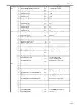
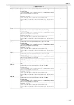
P002
STACKER
0
Punch feed motor phase A signal
1
Punch feed motor phase B signal
2
Punch feed motor phase A* signal
3
Punch feed motor phase B* signal
4
Tray motor CLK signal
5
Swing locking motor current switch IO
0: ON
6
Swing locking motor phase A signal
7
Swing locking motor phase B signal
P003
STACKER
0
TxD for external source
1
TxD for write
2
RxD for external
3
RxD for write
4
Punch connection detection
0: connected
5
OUT for punch communication
0: ON
6-7
Not used
P004
STACKER
0
Escape feed motor CLK(IRQ0*)
1
Trailing edge detection sensor (This mode is used at the time
of the punch unit installation.)
2
Saddle connection detection
0: connected
3
Upper tray FG(IRQ3*)
4
Swing lock HP sensor
1: HP
5
Swing height detection sensor
1: HP
6
Front cover open/close sensor
0: open
7
Gear change HP sensor
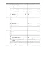
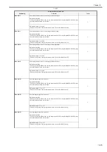
P005
STACKER
0
TxD for punch communication
1
RxD for punch communication
2
IN for punch dommunication (IRQ2*)
0: ON
3-7
Not used
P006
STACKER
0
Not used
1
Lower tray motor LOCK
0: locked
2
Not used
3
Lower tray motor ON
0: ON
4
Not used
5
Motor standby signal
0: ON
6-7
Not used
P007
STACKER
0-7
Not used
P008
STACKER
0
Lower tray area sensor 1
0: detected
1
Lower tray area sensor 2
0: detected
2
Lower tray area sensor 3
0: detected
3
Not used
4
Punch feed motor CLK (IRQ4*)
5
Lower tray FG (IRQ5*)
6
Inlet feed motor lock input (IRQ6*)
7
Stack edginng motor clock input (IRQ7*)
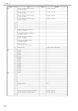
P009
STACKER
0
Not used
1
Lower tray paper surface sensor
0: paper present
2
1700-sheet paper surface sensor
0: paper present
3
Upper tray interlock
1: error
4
Upper tray area sensor 1
0: detected
5
Upper tray area sensor 2
0: detected
6
Upper tray area sensor 3
0: detected
7
Not used
P010
STACKER
0
Inlet feed motor current switch I1
0: ON
1
Inlet feed motor current switch I0
0: ON
2
Punch feed motor current switch I1
0: ON
3
Punch feed motor current switch I0
0: ON
4
Punch feed motor standby
0: ON
5
Escape feed motor I0
0: ON
6
Escape feed motor I1
0: ON
7
Escape feed motor standby
0: ON
Address
Controller
Bit
Description
Remarks
Содержание imagePRESS C1
Страница 1: ...Oct 22 2008 Service Manual imagePRESS C1 Series ...
Страница 2: ......
Страница 6: ......
Страница 38: ...Contents ...
Страница 39: ...Chapter 1 Introduction ...
Страница 40: ......
Страница 42: ......
Страница 72: ...Chapter 1 1 30 F 1 18 ...
Страница 85: ...Chapter 1 1 43 T 1 26 ...
Страница 88: ......
Страница 89: ...Chapter 2 Installation ...
Страница 90: ......
Страница 94: ......
Страница 234: ......
Страница 235: ...Chapter 3 Basic Operation ...
Страница 236: ......
Страница 238: ......
Страница 244: ......
Страница 245: ...Chapter 4 Main Controller ...
Страница 246: ......
Страница 248: ......
Страница 276: ...Chapter 5 Original Exposure System ...
Страница 277: ......
Страница 332: ...Chapter 6 Laser Exposure ...
Страница 333: ......
Страница 342: ...Chapter 6 6 8 F 6 10 1 Laser Light 2 Laser Shutter 3 Laser Shutter Lever 1 1 2 2 1 2 3 3 3 3 ...
Страница 344: ...Chapter 7 Image Formation ...
Страница 345: ......
Страница 431: ...Chapter 7 7 82 ...
Страница 462: ...Chapter 8 Pickup Feeding System ...
Страница 463: ......
Страница 503: ...Chapter 8 8 38 4 F 8 49 5 F 8 50 B Duplexing re pickup stop position 6 F 8 51 2 1 3 2 1 B 1 3 2 ...
Страница 504: ...Chapter 8 8 39 7 F 8 52 8 F 8 53 9 F 8 54 1 3 2 1 2 4 3 1 2 4 3 ...
Страница 505: ...Chapter 8 8 40 10 F 8 55 11 F 8 56 12 F 8 57 1 4 2 3 5 4 1 3 2 1 4 2 5 3 ...
Страница 506: ...Chapter 8 8 41 13 F 8 58 14 F 8 59 15 F 8 60 5 1 2 3 4 1 2 3 5 4 1 2 3 4 5 ...
Страница 507: ...Chapter 8 8 42 16 F 8 61 1 2 3 4 5 ...
Страница 509: ...Chapter 8 8 44 3 F 8 64 A Duplexing reversal position 4 F 8 65 2 1 A 2 1 ...
Страница 510: ...Chapter 8 8 45 5 F 8 66 6 F 8 67 2 1 2 1 ...
Страница 511: ...Chapter 8 8 46 7 F 8 68 8 F 8 69 3 2 1 3 2 1 ...
Страница 512: ...Chapter 8 8 47 9 F 8 70 10 F 8 71 3 2 1 2 3 1 ...
Страница 513: ...Chapter 8 8 48 11 F 8 72 B Duplexing re pickup stop position 12 F 8 73 3 2 B 1 3 1 2 ...
Страница 514: ...Chapter 8 8 49 13 F 8 74 14 F 8 75 1 2 3 1 2 3 ...
Страница 516: ...Chapter 8 8 51 F 8 77 SL3 M10 PS17 ...
Страница 533: ...Chapter 8 8 68 F 8 154 1 2 4 3 2 3 4 ...
Страница 534: ...Chapter 9 Fixing System ...
Страница 599: ...Chapter 10 Externals and Controls ...
Страница 642: ...Chapter 11 MEAP ...
Страница 643: ......
Страница 645: ......
Страница 695: ...Chapter 12 Maintenance and Inspection ...
Страница 696: ......
Страница 698: ......
Страница 700: ...Chapter 12 12 2 F 12 1 28 9 10 14 13 29 29 11 12 27 6 3 1 2 5 4 7 8 15 16 ...
Страница 701: ...Chapter 12 12 3 F 12 2 17 20 24 23 25 26 19 18 24 21 22 ...
Страница 704: ...Chapter 12 12 6 F 12 3 1 2 3 4 9 6 5 7 8 11 12 13 14 15 10 ...
Страница 715: ...Chapter 12 12 17 F 12 18 1 1 2 2 ...
Страница 716: ...Chapter 13 Standards and Adjustments ...
Страница 717: ......
Страница 719: ......
Страница 732: ...Chapter 14 Correcting Faulty Images ...
Страница 829: ...Chapter 14 14 94 F 14 93 J406 J206 J209 J203 J92 J3802 J57 J84 J91 J52 J79 J203 J204 J208 J201 J551 J1168 J115 ...
Страница 834: ...Chapter 14 14 99 F 14 98 J420 J432 J423 J422 J3417 J3415 J421 J427 J426 J454 J430 J425 J3410 J431 J425 J429 J433 J3416 ...
Страница 848: ...Chapter 14 14 113 F 14 112 J406 J206 J209 J203 J92 J3802 J57 J84 J91 J52 J79 J203 J204 J208 J201 J551 J1168 J115 ...
Страница 862: ...Chapter 15 Self Diagnosis ...
Страница 894: ...Chapter 16 Service Mode ...
Страница 895: ......
Страница 1222: ...Chapter 17 Upgrading ...
Страница 1223: ......
Страница 1225: ......
Страница 1256: ...Chapter 17 17 31 F 17 65 2 Turn off the main power switch and remove the USB device ...
Страница 1257: ...Chapter 18 Service Tools ...
Страница 1258: ...Contents Contents 18 1 Service Tools 18 1 18 1 1 Special Tools 18 1 18 1 2 Solvents and Oils 18 2 ...
Страница 1262: ......
Страница 1263: ......
Страница 1264: ...Oct 22 2008 ...
Страница 1265: ......


