


Chapter 13
13-7
F-13-14
9) Execute the service mode COPIER > FUNCTION > DPC > OFST.
10) Return the value of the service mode COPIER > FUNCTION > IN-
STALL > AINR-OFF as '0'.
11) Turn OFF the main power switch.
12) Attach the potential sensor onto the main body.
13.3.4 After Replacing the Pre-transfer Charging
Assembly
0014-0427
imagePRESS C1 P / imagePRESS C1
Execute the service mode (pre-transfer charging wire cleaning: COPIER >
FUNCTION > CLEANING > WIRE-CLN).
13.3.5 After Replacing the Waste Toner Box
0014-0800
imagePRESS C1 P / imagePRESS C1
1) Attach the new waste toner box onto the main body.
2) Execute the service mode (waste toner counter clear: COPIER >FUNC-
TION>CLEAR>WST-TN-CLR) and set the waste toner counter value as
'0'.
13.3.6 After Replacing the Secondary Transfer Roller
Waste Toner Case
0014-0805
imagePRESS C1 P / imagePRESS C1 / imagePRESS C1+ (Printer) / image-
PRESS C1+
1) Attach the new waste toner case or the empty waste toner case of which
waste toner is disposed onto the main body.
2) Execute the service mode (waste toner counter clear: COPIER > COUN-
TER > MISC > 2TC-BOX) and set the waste toner counter value as '0'.
13.3.7 After Replacing the Photosensitive Drum
0014-3199
imagePRESS C1 P / imagePRESS C1 / imagePRESS C1+ (Printer) / image-
PRESS C1+
Follow the procedure below to replace the photosensitive drum.
1) Turn on the main power switch.
2) Select the following items in the Service Mode and then hit OK.
3) Run the service mode for drum replacement mode enforcement execution
(COPIER > FUNCTION > DCP > DRM-RSET).
4) Run automatic gradation correction (full correction).
13.3.8 Replacing the Waste Toner Sensor
0014-8931
imagePRESS C1 P / imagePRESS C1 / imagePRESS C1+ (Printer) / image-
PRESS C1+
1) Execute the service mode (high-voltage offset adjustment: COPIER >
FUNCTION > MISC-P > HV-ADOFS).
Waste toner sensor offset adjustment service mode is not an independent
service mode. Instead, waste toner sensor offset adjustment is performed by
this adjustment (high-voltage offset adjustment). Therefore, when replacing
the waste toner sensor, execute this adjustment service mode. If toner is left
inside the waste toner bottle here, toner adjustment cannot be carried out
properly, resulting in an error code in some cases (E0013-0006: waste toner
sensor adjustment error). Be sure to execute this service mode after removing
the waste toner bottle from the main body.
13.3.9 After Replacing the ATR Sensor
0014-8932
imagePRESS C1 P / imagePRESS C1 / imagePRESS C1+ (Printer) / image-
PRESS C1+
Follow the procedure below to replace the ATR sensor.
1) Replace the color developing assembly (Y, M, C).
2) Turn on the main power switch.
3) Run automatic gradation correction (full correction).
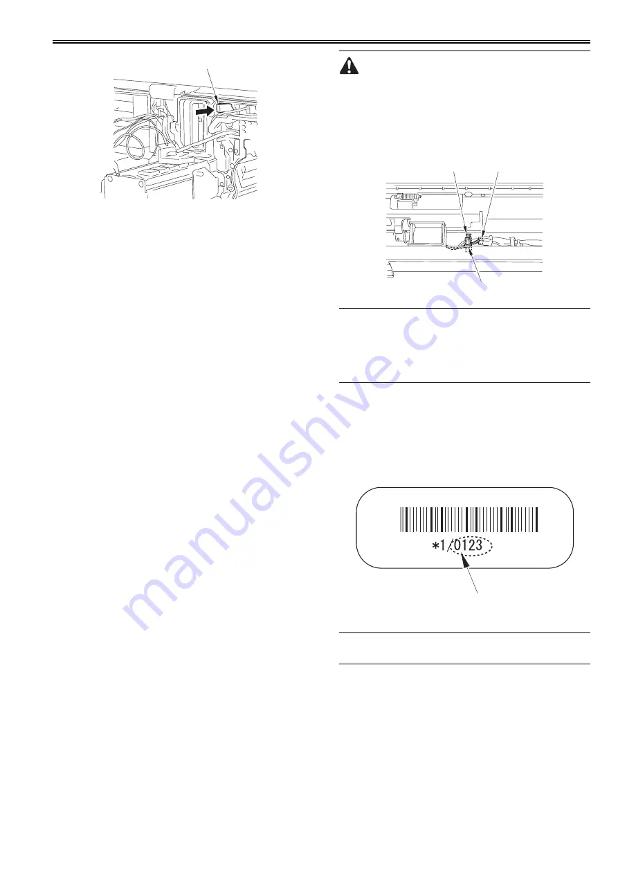
When Installing the ATR Sensor
* Be careful not to touch the developing cylinder, which can cause image
fault.
Upon installation of the ATR sensor, make sure to move the developing cyl-
inder away from the mounting location of the sensor by rotating the devel-
oping rotary clockwise.
* When plugging in the connector [1], wrap the harness [3] around the wire
saddle [2] once.
F-13-15
13.3.10 After Replacing the Patch Image Reading Sensor
0014-8933
imagePRESS C1 P / imagePRESS C1 / imagePRESS C1+ (Printer) / image-
PRESS C1+
Run the following items in the Service Mode after replacing the patch image
scan sensor.
Service Mode (Patch Detection Sensor Default Correction) :
COPIER > ADJUST > DENS > ALF-F <for patch image scan sensor
(front)>
COPIER > ADJUST > DENS > ALF-C <for patch image scan sensor (cent-
er)>
COPIER > ADJUST > DENS > ALF-R <for patch image scan sensor (rear)>
This sensor unit comes with the following correction value labels (3 in total).
The labels contain correction values for each sensor (front, center and rear).
Enter the label values (4 digits) [1] using the above service mode.
After entering the values, put the labels onto the new sensor unit.
F-13-16
13.4 Fixing System
13.4.1 Checking the Nip Width
0012-0899
imagePRESS C1 P / imagePRESS C1 / imagePRESS C1+ (Printer) / image-
PRESS C1+
The nip width cannot be adjusted at the field.
When replacing the fixing belt/fixing roller, or a fixing failure occurs, check
that there is no problem with the output result of the nip width (COPIER >
FUNCTION > FIXING > NIP-CHK).
1. Set a duplexing coated paper (equivalent to 120 to 128 g) in the manual
feed tray.
2. Execute the foregoing service mode.
3. Measure the nip width of the output paper (cyan solid image).
4. Check that the nip width(A,B) is within the range of reference values
(4.5 mm +/-1).
[1]
[2]
[1]
[3]
[1]
Содержание imagePRESS C1
Страница 1: ...Oct 22 2008 Service Manual imagePRESS C1 Series ...
Страница 2: ......
Страница 6: ......
Страница 38: ...Contents ...
Страница 39: ...Chapter 1 Introduction ...
Страница 40: ......
Страница 42: ......
Страница 72: ...Chapter 1 1 30 F 1 18 ...
Страница 85: ...Chapter 1 1 43 T 1 26 ...
Страница 88: ......
Страница 89: ...Chapter 2 Installation ...
Страница 90: ......
Страница 94: ......
Страница 234: ......
Страница 235: ...Chapter 3 Basic Operation ...
Страница 236: ......
Страница 238: ......
Страница 244: ......
Страница 245: ...Chapter 4 Main Controller ...
Страница 246: ......
Страница 248: ......
Страница 276: ...Chapter 5 Original Exposure System ...
Страница 277: ......
Страница 332: ...Chapter 6 Laser Exposure ...
Страница 333: ......
Страница 342: ...Chapter 6 6 8 F 6 10 1 Laser Light 2 Laser Shutter 3 Laser Shutter Lever 1 1 2 2 1 2 3 3 3 3 ...
Страница 344: ...Chapter 7 Image Formation ...
Страница 345: ......
Страница 431: ...Chapter 7 7 82 ...
Страница 462: ...Chapter 8 Pickup Feeding System ...
Страница 463: ......
Страница 503: ...Chapter 8 8 38 4 F 8 49 5 F 8 50 B Duplexing re pickup stop position 6 F 8 51 2 1 3 2 1 B 1 3 2 ...
Страница 504: ...Chapter 8 8 39 7 F 8 52 8 F 8 53 9 F 8 54 1 3 2 1 2 4 3 1 2 4 3 ...
Страница 505: ...Chapter 8 8 40 10 F 8 55 11 F 8 56 12 F 8 57 1 4 2 3 5 4 1 3 2 1 4 2 5 3 ...
Страница 506: ...Chapter 8 8 41 13 F 8 58 14 F 8 59 15 F 8 60 5 1 2 3 4 1 2 3 5 4 1 2 3 4 5 ...
Страница 507: ...Chapter 8 8 42 16 F 8 61 1 2 3 4 5 ...
Страница 509: ...Chapter 8 8 44 3 F 8 64 A Duplexing reversal position 4 F 8 65 2 1 A 2 1 ...
Страница 510: ...Chapter 8 8 45 5 F 8 66 6 F 8 67 2 1 2 1 ...
Страница 511: ...Chapter 8 8 46 7 F 8 68 8 F 8 69 3 2 1 3 2 1 ...
Страница 512: ...Chapter 8 8 47 9 F 8 70 10 F 8 71 3 2 1 2 3 1 ...
Страница 513: ...Chapter 8 8 48 11 F 8 72 B Duplexing re pickup stop position 12 F 8 73 3 2 B 1 3 1 2 ...
Страница 514: ...Chapter 8 8 49 13 F 8 74 14 F 8 75 1 2 3 1 2 3 ...
Страница 516: ...Chapter 8 8 51 F 8 77 SL3 M10 PS17 ...
Страница 533: ...Chapter 8 8 68 F 8 154 1 2 4 3 2 3 4 ...
Страница 534: ...Chapter 9 Fixing System ...
Страница 599: ...Chapter 10 Externals and Controls ...
Страница 642: ...Chapter 11 MEAP ...
Страница 643: ......
Страница 645: ......
Страница 695: ...Chapter 12 Maintenance and Inspection ...
Страница 696: ......
Страница 698: ......
Страница 700: ...Chapter 12 12 2 F 12 1 28 9 10 14 13 29 29 11 12 27 6 3 1 2 5 4 7 8 15 16 ...
Страница 701: ...Chapter 12 12 3 F 12 2 17 20 24 23 25 26 19 18 24 21 22 ...
Страница 704: ...Chapter 12 12 6 F 12 3 1 2 3 4 9 6 5 7 8 11 12 13 14 15 10 ...
Страница 715: ...Chapter 12 12 17 F 12 18 1 1 2 2 ...
Страница 716: ...Chapter 13 Standards and Adjustments ...
Страница 717: ......
Страница 719: ......
Страница 732: ...Chapter 14 Correcting Faulty Images ...
Страница 829: ...Chapter 14 14 94 F 14 93 J406 J206 J209 J203 J92 J3802 J57 J84 J91 J52 J79 J203 J204 J208 J201 J551 J1168 J115 ...
Страница 834: ...Chapter 14 14 99 F 14 98 J420 J432 J423 J422 J3417 J3415 J421 J427 J426 J454 J430 J425 J3410 J431 J425 J429 J433 J3416 ...
Страница 848: ...Chapter 14 14 113 F 14 112 J406 J206 J209 J203 J92 J3802 J57 J84 J91 J52 J79 J203 J204 J208 J201 J551 J1168 J115 ...
Страница 862: ...Chapter 15 Self Diagnosis ...
Страница 894: ...Chapter 16 Service Mode ...
Страница 895: ......
Страница 1222: ...Chapter 17 Upgrading ...
Страница 1223: ......
Страница 1225: ......
Страница 1256: ...Chapter 17 17 31 F 17 65 2 Turn off the main power switch and remove the USB device ...
Страница 1257: ...Chapter 18 Service Tools ...
Страница 1258: ...Contents Contents 18 1 Service Tools 18 1 18 1 1 Special Tools 18 1 18 1 2 Solvents and Oils 18 2 ...
Страница 1262: ......
Страница 1263: ......
Страница 1264: ...Oct 22 2008 ...
Страница 1265: ......


