


Chapter 7
7-110
F-7-255
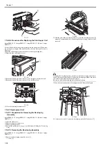
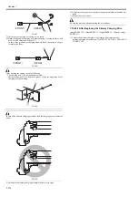
4) Remove the ATR sensor unit [1].
- 1 connector [2]
- 1 edge saddle [3]
- 2 screws [4]
F-7-256
5) Remove the ATR sensor [1].
- 2 screws [2]
F-7-257
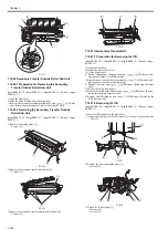
Points to Note when Attaching the ATR Sensor
When connecting the connector [1], coil the wire saddle [2] with harness [3]
(1 turn).
F-7-258
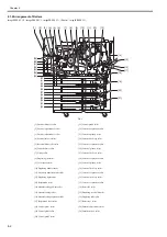
7.14.39.3 After Replacing the ATR Sensor
0014-3694
imagePRESS C1 P / imagePRESS C1 / imagePRESS C1+ (Printer) / image-
PRESS C1+
Perform the following steps when replacing the ATR sensor.
Follow the procedure below to replace the ATR sensor.
1) Replace the color developing assembly (Y, M, C).
2) Turn on the main power switch.
3) Run automatic gradation correction (full correction).
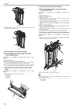
When Installing the ATR Sensor
* Be careful not to touch the developing cylinder, which can cause image
fault.
Upon installation of the ATR sensor, make sure to move the developing
cylinder away from the mounting location of the sensor by rotating the
developing rotary clockwise.
* When plugging in the connector [1], wrap the harness [3] around the
wire saddle [2] once.
F-7-259
7.14.40 Drum Thermal Sensor Unit
7.14.40.1 Preparation for Removing the Drum Thermal
Sensor Unit
0014-0066
imagePRESS C1 P / imagePRESS C1 / imagePRESS C1+ (Printer) / image-
PRESS C1+
1) Open the front cover.
2) Detach the process unit cover.
3) Lift the hopper unit.
4) Pull out the process unit.
Reference [Sliding the Processing
Unit]
5) Remove the primary charging assembly.
Reference [Re-
moving the Primary Corona Assembly]
6) Remove the pre-transfer charging assembly.
Reference [Re-
moving the pre-transfer corona assembly]
7) Remove the drum unit.
Reference [Removing the Drum
Unit]
7.14.40.2 Removing the Drum Thermal Sensor Unit
0014-0067
imagePRESS C1 P / imagePRESS C1 / imagePRESS C1+ (Printer) / image-
PRESS C1+
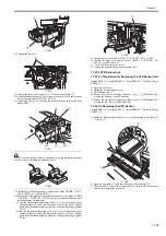
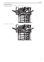
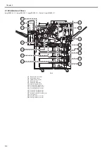
1) Remove the process unit guide [1].
- 2 screws [2]
F-7-260
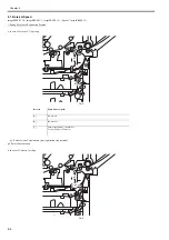
2) Remove the duct [1] by shifting it in the direction of the arrow.
- 1 screw [2]
F-7-261
3) Remove the drum thermal sensor unit [1].
- 1 connector [2]
- 2 screws [3]
[1]
[2]
[3]
[1]
[2]
[3]
[4]
[4]
[1]
[2]
[2]
[2]
[1]
[3]
[2]
[1]
[3]
[2]
[2]
[1]
[2]
[1]
Содержание imagePRESS C1
Страница 1: ...Oct 22 2008 Service Manual imagePRESS C1 Series ...
Страница 2: ......
Страница 6: ......
Страница 38: ...Contents ...
Страница 39: ...Chapter 1 Introduction ...
Страница 40: ......
Страница 42: ......
Страница 72: ...Chapter 1 1 30 F 1 18 ...
Страница 85: ...Chapter 1 1 43 T 1 26 ...
Страница 88: ......
Страница 89: ...Chapter 2 Installation ...
Страница 90: ......
Страница 94: ......
Страница 234: ......
Страница 235: ...Chapter 3 Basic Operation ...
Страница 236: ......
Страница 238: ......
Страница 244: ......
Страница 245: ...Chapter 4 Main Controller ...
Страница 246: ......
Страница 248: ......
Страница 276: ...Chapter 5 Original Exposure System ...
Страница 277: ......
Страница 332: ...Chapter 6 Laser Exposure ...
Страница 333: ......
Страница 342: ...Chapter 6 6 8 F 6 10 1 Laser Light 2 Laser Shutter 3 Laser Shutter Lever 1 1 2 2 1 2 3 3 3 3 ...
Страница 344: ...Chapter 7 Image Formation ...
Страница 345: ......
Страница 431: ...Chapter 7 7 82 ...
Страница 462: ...Chapter 8 Pickup Feeding System ...
Страница 463: ......
Страница 503: ...Chapter 8 8 38 4 F 8 49 5 F 8 50 B Duplexing re pickup stop position 6 F 8 51 2 1 3 2 1 B 1 3 2 ...
Страница 504: ...Chapter 8 8 39 7 F 8 52 8 F 8 53 9 F 8 54 1 3 2 1 2 4 3 1 2 4 3 ...
Страница 505: ...Chapter 8 8 40 10 F 8 55 11 F 8 56 12 F 8 57 1 4 2 3 5 4 1 3 2 1 4 2 5 3 ...
Страница 506: ...Chapter 8 8 41 13 F 8 58 14 F 8 59 15 F 8 60 5 1 2 3 4 1 2 3 5 4 1 2 3 4 5 ...
Страница 507: ...Chapter 8 8 42 16 F 8 61 1 2 3 4 5 ...
Страница 509: ...Chapter 8 8 44 3 F 8 64 A Duplexing reversal position 4 F 8 65 2 1 A 2 1 ...
Страница 510: ...Chapter 8 8 45 5 F 8 66 6 F 8 67 2 1 2 1 ...
Страница 511: ...Chapter 8 8 46 7 F 8 68 8 F 8 69 3 2 1 3 2 1 ...
Страница 512: ...Chapter 8 8 47 9 F 8 70 10 F 8 71 3 2 1 2 3 1 ...
Страница 513: ...Chapter 8 8 48 11 F 8 72 B Duplexing re pickup stop position 12 F 8 73 3 2 B 1 3 1 2 ...
Страница 514: ...Chapter 8 8 49 13 F 8 74 14 F 8 75 1 2 3 1 2 3 ...
Страница 516: ...Chapter 8 8 51 F 8 77 SL3 M10 PS17 ...
Страница 533: ...Chapter 8 8 68 F 8 154 1 2 4 3 2 3 4 ...
Страница 534: ...Chapter 9 Fixing System ...
Страница 599: ...Chapter 10 Externals and Controls ...
Страница 642: ...Chapter 11 MEAP ...
Страница 643: ......
Страница 645: ......
Страница 695: ...Chapter 12 Maintenance and Inspection ...
Страница 696: ......
Страница 698: ......
Страница 700: ...Chapter 12 12 2 F 12 1 28 9 10 14 13 29 29 11 12 27 6 3 1 2 5 4 7 8 15 16 ...
Страница 701: ...Chapter 12 12 3 F 12 2 17 20 24 23 25 26 19 18 24 21 22 ...
Страница 704: ...Chapter 12 12 6 F 12 3 1 2 3 4 9 6 5 7 8 11 12 13 14 15 10 ...
Страница 715: ...Chapter 12 12 17 F 12 18 1 1 2 2 ...
Страница 716: ...Chapter 13 Standards and Adjustments ...
Страница 717: ......
Страница 719: ......
Страница 732: ...Chapter 14 Correcting Faulty Images ...
Страница 829: ...Chapter 14 14 94 F 14 93 J406 J206 J209 J203 J92 J3802 J57 J84 J91 J52 J79 J203 J204 J208 J201 J551 J1168 J115 ...
Страница 834: ...Chapter 14 14 99 F 14 98 J420 J432 J423 J422 J3417 J3415 J421 J427 J426 J454 J430 J425 J3410 J431 J425 J429 J433 J3416 ...
Страница 848: ...Chapter 14 14 113 F 14 112 J406 J206 J209 J203 J92 J3802 J57 J84 J91 J52 J79 J203 J204 J208 J201 J551 J1168 J115 ...
Страница 862: ...Chapter 15 Self Diagnosis ...
Страница 894: ...Chapter 16 Service Mode ...
Страница 895: ......
Страница 1222: ...Chapter 17 Upgrading ...
Страница 1223: ......
Страница 1225: ......
Страница 1256: ...Chapter 17 17 31 F 17 65 2 Turn off the main power switch and remove the USB device ...
Страница 1257: ...Chapter 18 Service Tools ...
Страница 1258: ...Contents Contents 18 1 Service Tools 18 1 18 1 1 Special Tools 18 1 18 1 2 Solvents and Oils 18 2 ...
Страница 1262: ......
Страница 1263: ......
Страница 1264: ...Oct 22 2008 ...
Страница 1265: ......