


Chapter 10
10-26
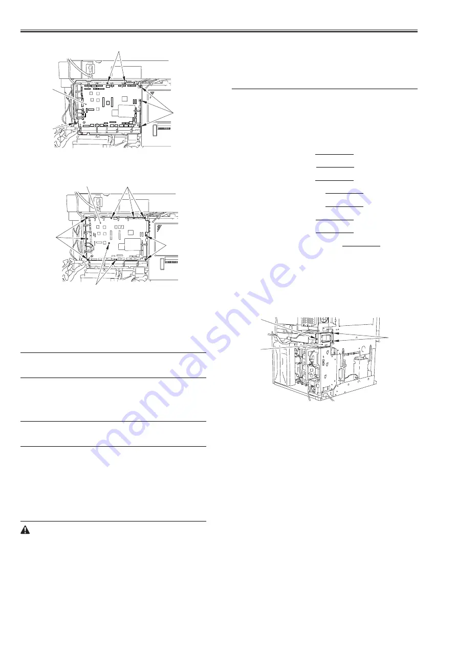
F-10-99
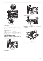
8) Remove the DC controller PCB [1].
- 10 screws [2]
F-10-100
10.5.6.3 After Replacing the DC controller PCB
0014-3692
imagePRESS C1 P / imagePRESS C1 / imagePRESS C1+ (Printer) / image-
PRESS C1+
1) Upload the 'SramDCON.bin' from 'upload the backup data' using SST and
save it.
MEMO:
For detailed uploading procedures, see the chapter of upgrading in the man-
ual.
2) After replacing the DC controller PCB, download the latest system soft-
ware using SST.
3) Execute RAM clear of the DC controller PCB by the service mode below.
COPIER > FUNCTION > CLEAR > DC-CON
4) Select the uploaded file from 'download the backup data' and download it
using SST.
MEMO:
For detailed downloading procedures, see the chapter of upgrading in the
manual.
5) Select the uploaded file from 'download the backup data' and download it
using SST.
6) Remove the waste toner in the waste toner receptacle (waste toner bottle,
secondary transfer outside roller waste toner receptacle), and then clear
the 2 types of waste toner counter (see Note 1).
7) Execute the service mode (high-voltage offset adjustment: COPIER >
FUNCTION > MISC-P > HV-ADOFS) (see Note 2).
8) Execute the service mode (compulsory initial rotation: COPIER > FUNC-
TION > MISC-P-INTR-FX).
9) Execute the full correction of the automatic gradation correction (image
characteristics correction control).
Note 1:
You cannot re-enter the waste toner counter (waste toner bottle, secondary
transfer roller waste toner receptacle) in the service mode. Therefore, in or-
der to replace the DC controller PCB or clear the RAM, clear the 2 types of
the waste toner counter using the following service modes:
- Waste toner bottle counter clear: COPIER > COUNTER > MISC > WST-
TNR
- Secondary transfer outside roller waste toner receptacle counter clear:
COPIER > COUNTER > MISC > 2TC-BOX
Note2:
On execution of this service mode, the waste toner sensor offset adjustment
is executed.
If toner is left inside the waste toner bottle here, toner adjustment cannot be
carried out properly, resulting in an error code in some cases (E0013-0006:
waste toner sensor adjustment error).
Be sure to execute this service mode after removing the waste toner bottle
from the main body.
10.5.7 Leakage Breaker
10.5.7.1 Preparation for Removing the Leakage Breaker
0013-9405
imagePRESS C1 P / imagePRESS C1 / imagePRESS C1+ (Printer) / image-
PRESS C1+
1) Remove the decurler.
2) Remove the left upper cover.
Reference [Removing the
Left Upper Cover]
3) Remove the left middle cover.
Reference [Removing the
Left Middle Cover]
4) Remove the left lower cover.
Reference [Removing the
Left Lower Cover]
5) Remove the left rear upper cover.
Reference [Removing
the Left Rear Upper Cover]
6) Remove the left rear lower cover.
Reference [Removing
the Left Rear Lower Cover]
7) Remove the rear upper cover.
Reference [Removing the
Rear Upper Cover]
8) Remove the rear lower cover.
Reference [Removing the
Rear Lower Cover]
9) Remove the DC power supply assembly.
Reference [Re-
moving the Power Supply Assembly]
10.5.7.2 Removing the Leakage Breaker
0013-9406
imagePRESS C1 P / imagePRESS C1 / imagePRESS C1+ (Printer) / image-
PRESS C1+
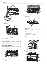
1) Move the decurler connector plate [1] so that the screw beneath it can be
seen.
- 3 screws [2]
F-10-101
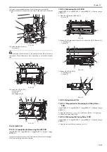
2) Remove the decurler connector plate cut-off [1], and remove the AC driv-
er box [2].
- 11 screws [3]
[2]
[2]
[2]
[1]
[1]
[2]
[2]
[2]
[2]
[1]
[2]
[2]
Содержание imagePRESS C1
Страница 1: ...Oct 22 2008 Service Manual imagePRESS C1 Series ...
Страница 2: ......
Страница 6: ......
Страница 38: ...Contents ...
Страница 39: ...Chapter 1 Introduction ...
Страница 40: ......
Страница 42: ......
Страница 72: ...Chapter 1 1 30 F 1 18 ...
Страница 85: ...Chapter 1 1 43 T 1 26 ...
Страница 88: ......
Страница 89: ...Chapter 2 Installation ...
Страница 90: ......
Страница 94: ......
Страница 234: ......
Страница 235: ...Chapter 3 Basic Operation ...
Страница 236: ......
Страница 238: ......
Страница 244: ......
Страница 245: ...Chapter 4 Main Controller ...
Страница 246: ......
Страница 248: ......
Страница 276: ...Chapter 5 Original Exposure System ...
Страница 277: ......
Страница 332: ...Chapter 6 Laser Exposure ...
Страница 333: ......
Страница 342: ...Chapter 6 6 8 F 6 10 1 Laser Light 2 Laser Shutter 3 Laser Shutter Lever 1 1 2 2 1 2 3 3 3 3 ...
Страница 344: ...Chapter 7 Image Formation ...
Страница 345: ......
Страница 431: ...Chapter 7 7 82 ...
Страница 462: ...Chapter 8 Pickup Feeding System ...
Страница 463: ......
Страница 503: ...Chapter 8 8 38 4 F 8 49 5 F 8 50 B Duplexing re pickup stop position 6 F 8 51 2 1 3 2 1 B 1 3 2 ...
Страница 504: ...Chapter 8 8 39 7 F 8 52 8 F 8 53 9 F 8 54 1 3 2 1 2 4 3 1 2 4 3 ...
Страница 505: ...Chapter 8 8 40 10 F 8 55 11 F 8 56 12 F 8 57 1 4 2 3 5 4 1 3 2 1 4 2 5 3 ...
Страница 506: ...Chapter 8 8 41 13 F 8 58 14 F 8 59 15 F 8 60 5 1 2 3 4 1 2 3 5 4 1 2 3 4 5 ...
Страница 507: ...Chapter 8 8 42 16 F 8 61 1 2 3 4 5 ...
Страница 509: ...Chapter 8 8 44 3 F 8 64 A Duplexing reversal position 4 F 8 65 2 1 A 2 1 ...
Страница 510: ...Chapter 8 8 45 5 F 8 66 6 F 8 67 2 1 2 1 ...
Страница 511: ...Chapter 8 8 46 7 F 8 68 8 F 8 69 3 2 1 3 2 1 ...
Страница 512: ...Chapter 8 8 47 9 F 8 70 10 F 8 71 3 2 1 2 3 1 ...
Страница 513: ...Chapter 8 8 48 11 F 8 72 B Duplexing re pickup stop position 12 F 8 73 3 2 B 1 3 1 2 ...
Страница 514: ...Chapter 8 8 49 13 F 8 74 14 F 8 75 1 2 3 1 2 3 ...
Страница 516: ...Chapter 8 8 51 F 8 77 SL3 M10 PS17 ...
Страница 533: ...Chapter 8 8 68 F 8 154 1 2 4 3 2 3 4 ...
Страница 534: ...Chapter 9 Fixing System ...
Страница 599: ...Chapter 10 Externals and Controls ...
Страница 642: ...Chapter 11 MEAP ...
Страница 643: ......
Страница 645: ......
Страница 695: ...Chapter 12 Maintenance and Inspection ...
Страница 696: ......
Страница 698: ......
Страница 700: ...Chapter 12 12 2 F 12 1 28 9 10 14 13 29 29 11 12 27 6 3 1 2 5 4 7 8 15 16 ...
Страница 701: ...Chapter 12 12 3 F 12 2 17 20 24 23 25 26 19 18 24 21 22 ...
Страница 704: ...Chapter 12 12 6 F 12 3 1 2 3 4 9 6 5 7 8 11 12 13 14 15 10 ...
Страница 715: ...Chapter 12 12 17 F 12 18 1 1 2 2 ...
Страница 716: ...Chapter 13 Standards and Adjustments ...
Страница 717: ......
Страница 719: ......
Страница 732: ...Chapter 14 Correcting Faulty Images ...
Страница 829: ...Chapter 14 14 94 F 14 93 J406 J206 J209 J203 J92 J3802 J57 J84 J91 J52 J79 J203 J204 J208 J201 J551 J1168 J115 ...
Страница 834: ...Chapter 14 14 99 F 14 98 J420 J432 J423 J422 J3417 J3415 J421 J427 J426 J454 J430 J425 J3410 J431 J425 J429 J433 J3416 ...
Страница 848: ...Chapter 14 14 113 F 14 112 J406 J206 J209 J203 J92 J3802 J57 J84 J91 J52 J79 J203 J204 J208 J201 J551 J1168 J115 ...
Страница 862: ...Chapter 15 Self Diagnosis ...
Страница 894: ...Chapter 16 Service Mode ...
Страница 895: ......
Страница 1222: ...Chapter 17 Upgrading ...
Страница 1223: ......
Страница 1225: ......
Страница 1256: ...Chapter 17 17 31 F 17 65 2 Turn off the main power switch and remove the USB device ...
Страница 1257: ...Chapter 18 Service Tools ...
Страница 1258: ...Contents Contents 18 1 Service Tools 18 1 18 1 1 Special Tools 18 1 18 1 2 Solvents and Oils 18 2 ...
Страница 1262: ......
Страница 1263: ......
Страница 1264: ...Oct 22 2008 ...
Страница 1265: ......


