


Chapter 13
13-11
13.5.4 After Replacing the HDD
0014-3735
imagePRESS C1 P / imagePRESS C1 / imagePRESS C1+ (Printer) / image-
PRESS C1+
1. If NSA (Net Spot Account) is not used:
1) Formatting the HDD
Start the equipment to the SafeMode (turn on the main power pressing
2+8 key).
Using the HD formatting function of the SST, format all the partitions.
(See the chapter on version upgrade for more details.)
2) Downloading the system software
Use SST to download system / Language / RUI. It can take about 5
minutes to restart after downloading.
2. If NSA (Net Spot Account) along with card reader is used:
A card ID for NSA is downloaded on the HDD. When replacing the HDD,
card data must be downloaded from the NSA again so that counting manage-
ment is possible in the NSA.
[Just as is in the case where NSA is not used (1.), after formatting the HDD
and downloading the system software different procedure must be followed.
1) HDD Formatting
Start the equipment to the SafeMode (turn on the main power pressing
2+8 key).
Using the HD formatting function of the SST, format all the partitions.
(See the chapter on version upgrade for more details.)
2) Downloading the System Software
Use SST to download system / Language / RUI. It can take about 5
minutes to restart after downloading.
3) In the Service Mode
Select: COPIER > FUNCTION > INSTALL > CARD.
4) Entering the Card Number
Enter the number of the first card of the cards used in divisional
management, and then press Enter. (E.g. If using cards numbered 1 to
1000 for divisional management, enter the first card's number, "1".)
5) Turn off the main power and then turn it back on.
6) Confirming the Count Management
In the User Mode, select "System Management Setup > Group ID
Management > Count Management" and confirm ID's numbered from
ID00000001 to ID00001000 have been created.
7) Setting Up Addresses
In the User Mode, select "System Management Setup > Net Work
Settings > TCP IP Setup > IP address" and set up IP address, gateway
address, and subnet mask.
8) Entering ID's
In "System Administrator Information Setup" in the User Mode, register
"System Management Group ID" and "System Management ID."
9) Turn off the main power and then turn it back on.
If the "System Management Group ID" and "System Management ID" is not
registered, "Card Registration to the Device" cannot be done when setting
Net Spot Accnout.
10) Downloading Card ID
While putting the equipment on stand-by, download card ID from the
NSA to be used for the repaired equipment.
11) Confirmation of Count Management
In the User System select: System Management Setup > Group ID Setup
> Count Management." Confirm that only ID's that have been
downloaded are displayed.
12) Confirmation of Performance
Try photocopying a document using the User Card registered at the NSA,
and confirm the card is counted in the counting device of the NSA.
13.5.5 Replacing the HV2, HV4, HV6-1 and HV6-2
0014-3049
imagePRESS C1 P / imagePRESS C1 / imagePRESS C1+ (Printer) / image-
PRESS C1+
1) Execute the service mode (high-voltage offset adjustment: COPIER >
FUNCTION > MISC-P > HV-ADOFS).
On execution of this service mode, the waste toner sensor offset adjustment
is executed. If toner is left inside the waste toner bottle here, toner adjustment
cannot be carried out properly, resulting in an error code in some cases
(E0013-0006: waste toner sensor adjustment error). Be sure to execute this
service mode after removing the waste toner bottle from the main body.
13.5.6 Inputting the Rank Value at Replacing the Paper
Thickness Sensor
0013-3425
imagePRESS C1 P / imagePRESS C1 / imagePRESS C1+ (Printer) / image-
PRESS C1+
Input the values corresponding to the characters on the label attached to the
new paper thickness sensor in the following service mode items.
- COPIER > ADJUST > MISC > DF-S-NK (Inputting the rank values for the
paper thickness sensor.)
13.6 Pickup/Feeding System
13.6.1 Vertical Registration Adjustment at Cassette
Pickup
0013-3422
imagePRESS C1 P / imagePRESS C1 / imagePRESS C1+ (Printer) / image-
PRESS C1+
Copy from each cassette, check if the left/right image margin are within the
standards.
When the value is not within the standard value, adjust it by the following
procedures.
1) Press the set release button, pull the cassette forward.
2) Open the right upper cover and right lower cover.
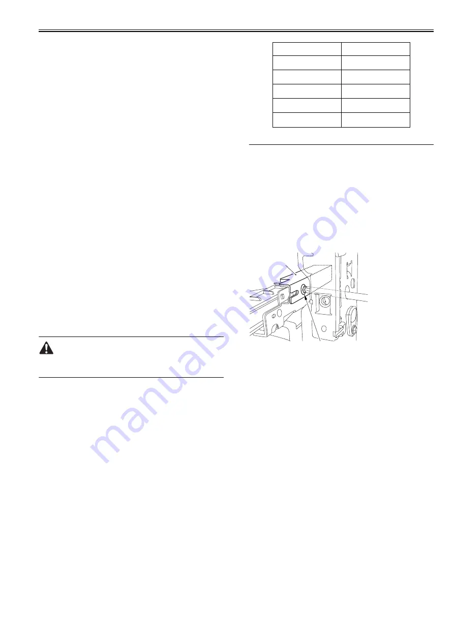
3) Insert the driver from the hole of the right front crossmember, loosen the
screw [1] and adjust the location of the adjusting plate [2].
F-13-32
Move the adjusting plate to the rear side: The left margin decreases.
Move the adjusting plate to the front side: The left margin increases.
4) Hold the screw.
5) Close the right cover (upper) and right cover (lower).
6) Mount the cassette.
13.6.2 Vertical Registration Adjustment at Manual Pickup
0013-3423
imagePRESS C1 P / imagePRESS C1 / imagePRESS C1+ (Printer) / image-
PRESS C1+
Copy from the manual tray, check if the left/right image margin are within
the standards.
When the value is not within the standard value, adjust it by the following
procedures.
1) Loosen one screw [1], move the fixing location of the slide guide [2] to
adjust the vertical registration.
Character on the label
DF-S-NK input value
A
1
B
2
C
3
D
4
E
5
[1]
[2]
Содержание imagePRESS C1
Страница 1: ...Oct 22 2008 Service Manual imagePRESS C1 Series ...
Страница 2: ......
Страница 6: ......
Страница 38: ...Contents ...
Страница 39: ...Chapter 1 Introduction ...
Страница 40: ......
Страница 42: ......
Страница 72: ...Chapter 1 1 30 F 1 18 ...
Страница 85: ...Chapter 1 1 43 T 1 26 ...
Страница 88: ......
Страница 89: ...Chapter 2 Installation ...
Страница 90: ......
Страница 94: ......
Страница 234: ......
Страница 235: ...Chapter 3 Basic Operation ...
Страница 236: ......
Страница 238: ......
Страница 244: ......
Страница 245: ...Chapter 4 Main Controller ...
Страница 246: ......
Страница 248: ......
Страница 276: ...Chapter 5 Original Exposure System ...
Страница 277: ......
Страница 332: ...Chapter 6 Laser Exposure ...
Страница 333: ......
Страница 342: ...Chapter 6 6 8 F 6 10 1 Laser Light 2 Laser Shutter 3 Laser Shutter Lever 1 1 2 2 1 2 3 3 3 3 ...
Страница 344: ...Chapter 7 Image Formation ...
Страница 345: ......
Страница 431: ...Chapter 7 7 82 ...
Страница 462: ...Chapter 8 Pickup Feeding System ...
Страница 463: ......
Страница 503: ...Chapter 8 8 38 4 F 8 49 5 F 8 50 B Duplexing re pickup stop position 6 F 8 51 2 1 3 2 1 B 1 3 2 ...
Страница 504: ...Chapter 8 8 39 7 F 8 52 8 F 8 53 9 F 8 54 1 3 2 1 2 4 3 1 2 4 3 ...
Страница 505: ...Chapter 8 8 40 10 F 8 55 11 F 8 56 12 F 8 57 1 4 2 3 5 4 1 3 2 1 4 2 5 3 ...
Страница 506: ...Chapter 8 8 41 13 F 8 58 14 F 8 59 15 F 8 60 5 1 2 3 4 1 2 3 5 4 1 2 3 4 5 ...
Страница 507: ...Chapter 8 8 42 16 F 8 61 1 2 3 4 5 ...
Страница 509: ...Chapter 8 8 44 3 F 8 64 A Duplexing reversal position 4 F 8 65 2 1 A 2 1 ...
Страница 510: ...Chapter 8 8 45 5 F 8 66 6 F 8 67 2 1 2 1 ...
Страница 511: ...Chapter 8 8 46 7 F 8 68 8 F 8 69 3 2 1 3 2 1 ...
Страница 512: ...Chapter 8 8 47 9 F 8 70 10 F 8 71 3 2 1 2 3 1 ...
Страница 513: ...Chapter 8 8 48 11 F 8 72 B Duplexing re pickup stop position 12 F 8 73 3 2 B 1 3 1 2 ...
Страница 514: ...Chapter 8 8 49 13 F 8 74 14 F 8 75 1 2 3 1 2 3 ...
Страница 516: ...Chapter 8 8 51 F 8 77 SL3 M10 PS17 ...
Страница 533: ...Chapter 8 8 68 F 8 154 1 2 4 3 2 3 4 ...
Страница 534: ...Chapter 9 Fixing System ...
Страница 599: ...Chapter 10 Externals and Controls ...
Страница 642: ...Chapter 11 MEAP ...
Страница 643: ......
Страница 645: ......
Страница 695: ...Chapter 12 Maintenance and Inspection ...
Страница 696: ......
Страница 698: ......
Страница 700: ...Chapter 12 12 2 F 12 1 28 9 10 14 13 29 29 11 12 27 6 3 1 2 5 4 7 8 15 16 ...
Страница 701: ...Chapter 12 12 3 F 12 2 17 20 24 23 25 26 19 18 24 21 22 ...
Страница 704: ...Chapter 12 12 6 F 12 3 1 2 3 4 9 6 5 7 8 11 12 13 14 15 10 ...
Страница 715: ...Chapter 12 12 17 F 12 18 1 1 2 2 ...
Страница 716: ...Chapter 13 Standards and Adjustments ...
Страница 717: ......
Страница 719: ......
Страница 732: ...Chapter 14 Correcting Faulty Images ...
Страница 829: ...Chapter 14 14 94 F 14 93 J406 J206 J209 J203 J92 J3802 J57 J84 J91 J52 J79 J203 J204 J208 J201 J551 J1168 J115 ...
Страница 834: ...Chapter 14 14 99 F 14 98 J420 J432 J423 J422 J3417 J3415 J421 J427 J426 J454 J430 J425 J3410 J431 J425 J429 J433 J3416 ...
Страница 848: ...Chapter 14 14 113 F 14 112 J406 J206 J209 J203 J92 J3802 J57 J84 J91 J52 J79 J203 J204 J208 J201 J551 J1168 J115 ...
Страница 862: ...Chapter 15 Self Diagnosis ...
Страница 894: ...Chapter 16 Service Mode ...
Страница 895: ......
Страница 1222: ...Chapter 17 Upgrading ...
Страница 1223: ......
Страница 1225: ......
Страница 1256: ...Chapter 17 17 31 F 17 65 2 Turn off the main power switch and remove the USB device ...
Страница 1257: ...Chapter 18 Service Tools ...
Страница 1258: ...Contents Contents 18 1 Service Tools 18 1 18 1 1 Special Tools 18 1 18 1 2 Solvents and Oils 18 2 ...
Страница 1262: ......
Страница 1263: ......
Страница 1264: ...Oct 22 2008 ...
Страница 1265: ......


