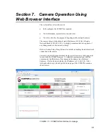
Section 7. Camera Operation Using Web Browser Interface
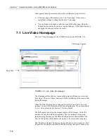
7-15
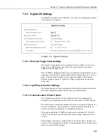
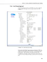
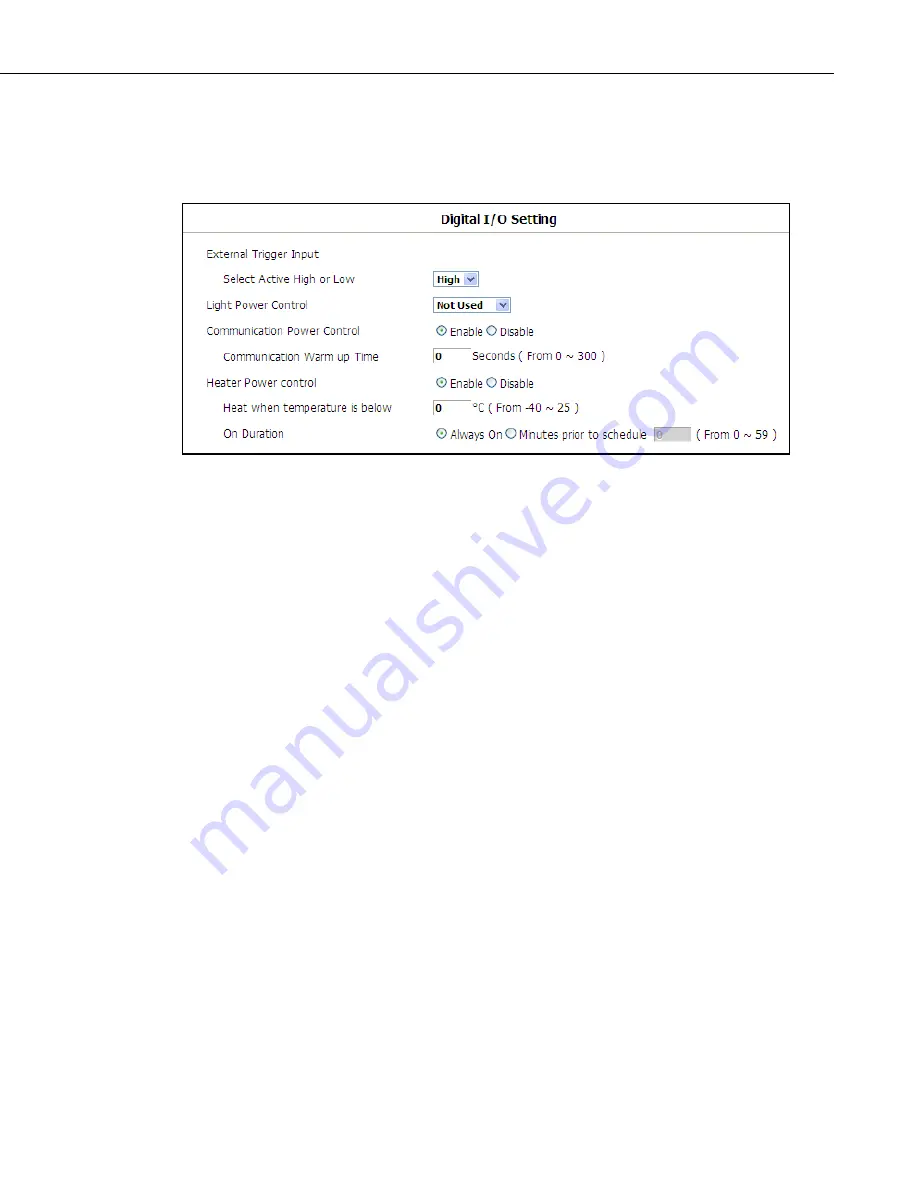
7.3.5 Digital I/O Settings
The Digital I/O sub menu (see FIGURE 7-16) allows the configuration of some
of the camera’s I/O signals.
FIGURE 7-16. Digital I/O Settings
7.3.5.1 External Trigger Input Settings
The external Trigger Input can be configured to Active High or Active Low.
When set to Active High, 0 volts will be the inactive state and a positive
voltage will be the active state.
The CC5MPX is shipped from the factory by default with a pull-down resistor
connected to the External Trigger Input and the External Trigger set to Active
High. With this default setting, when no signal is applied to the input the
External Trigger is inactive. A positive voltage is required to change to the
active state.
7.3.5.2 Light Power Control Settings
This feature had not yet been implemented at the time this manual was written.
Check the Campbell Scientific website for any possible updates.
7.3.5.3 Communication Power Control
The Communication Power Control setting controls the Communication
Switched Power Output line on the Power I/O cable of the CC5MPX camera.
The switch output is intended to manage the power to a communication device
such as a cell modem. This is useful in a solar powered site when there is a
need to limit power consumption of communication devices.
This option enables the CC5MPX to supply up to a maximum of 750 mA of
current. The voltage level will be the same as the camera’s input power (i.e.,
12 Vdc).
Some modems will require a warm up time or a period to time to register on a
network. The Communication Warm up Time parameter allows an appropriate
time to be entered for this purpose.
Содержание CC5MPX 6HULHV
Страница 2: ......
Страница 10: ...CC5MPX Table of Contents vi ...
Страница 12: ...Section 1 Introduction 1 2 ...
Страница 22: ...Section 3 Getting Started 3 8 FIGURE 3 7 CC5MPX Device Configuration Utility Settings Editor ...
Страница 28: ...Section 4 Cables Wiring 4 6 ...
Страница 36: ...Section 6 Camera Configuration 6 2 ...
Страница 69: ...Section 7 Camera Operation Using Web Browser Interface 7 33 FIGURE 7 30 External Trigger Setup Page ...
Страница 72: ...Section 7 Camera Operation Using Web Browser Interface 7 36 FIGURE 7 31 Motion Detection Page ...
Страница 84: ...Section 10 RS 485 Communications 10 2 ...
Страница 86: ...Section 11 PakBus Communications 11 2 ...
Страница 88: ...Section 12 Device Configuration Utility 12 2 FIGURE 12 2 Device Configuration Utility Screen ...
Страница 90: ...Section 13 Image Quality 13 2 ...
Страница 98: ...Section 15 Power Calculations and Timings 15 4 ...
Страница 104: ...Section 17 Remote Image Retrieval 17 4 ...
Страница 110: ...Section 19 Maintenance 19 4 FIGURE 19 5 Desiccant Location Location of Desiccant ...
Страница 116: ...Section 21 System Limitations 21 2 ...
Страница 122: ...Section 23 Quick Notes 23 4 ...
Страница 128: ...Appendix B CC5MPXWD Window Defroster Description B 2 FIGURE B 2 CC5MPXWD Window Defroster with Lens Tube Installed ...
Страница 129: ......


