


Section 4. Cables/Wiring
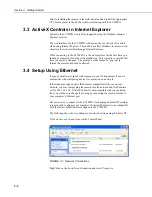
4-3
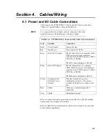
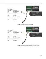
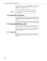
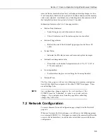
CC5MPXCBL1
Wire Color
Connection
Black
CR1000 Power G
Red CR1000
12V
Green CR1000
C2
White CR1000
C1
Yellow
Gray Terminal Block
Blue
Gray Terminal Block
Clear CR1000
G
FIGURE 4-1. Camera Connected to CR1000
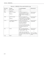
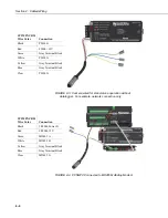
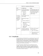
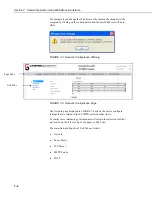
CC5MPXCBL1
Wire Color
Connection
Black
CR1000 Power G
Red CR1000
12V
Green CR1000
C2
White CR1000
C1
Yellow
Gray Terminal Block
Blue CR1000
C4
Clear CR1000
G
FIGURE 4-2. Connection Allows CR1000 to Trigger the Camera
Содержание CC5MPX 6HULHV
Страница 2: ......
Страница 10: ...CC5MPX Table of Contents vi ...
Страница 12: ...Section 1 Introduction 1 2 ...
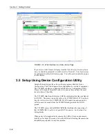
Страница 22: ...Section 3 Getting Started 3 8 FIGURE 3 7 CC5MPX Device Configuration Utility Settings Editor ...
Страница 28: ...Section 4 Cables Wiring 4 6 ...
Страница 36: ...Section 6 Camera Configuration 6 2 ...
Страница 69: ...Section 7 Camera Operation Using Web Browser Interface 7 33 FIGURE 7 30 External Trigger Setup Page ...
Страница 72: ...Section 7 Camera Operation Using Web Browser Interface 7 36 FIGURE 7 31 Motion Detection Page ...
Страница 84: ...Section 10 RS 485 Communications 10 2 ...
Страница 86: ...Section 11 PakBus Communications 11 2 ...
Страница 88: ...Section 12 Device Configuration Utility 12 2 FIGURE 12 2 Device Configuration Utility Screen ...
Страница 90: ...Section 13 Image Quality 13 2 ...
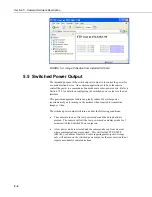
Страница 98: ...Section 15 Power Calculations and Timings 15 4 ...
Страница 104: ...Section 17 Remote Image Retrieval 17 4 ...
Страница 110: ...Section 19 Maintenance 19 4 FIGURE 19 5 Desiccant Location Location of Desiccant ...
Страница 116: ...Section 21 System Limitations 21 2 ...
Страница 122: ...Section 23 Quick Notes 23 4 ...
Страница 128: ...Appendix B CC5MPXWD Window Defroster Description B 2 FIGURE B 2 CC5MPXWD Window Defroster with Lens Tube Installed ...
Страница 129: ......


