EQUALISER
A six band parametric EQ module is available on every channel, group and main.
The frequency range for all bands is 20 Hz to 20 kHz and the available range in gain is -18 dB to +18 dB. The Q control
for the bell curve can be set at: 0.3, 0.5, 0.7, 1, 2, 3, 5, 7 or 10, and for all other bands is set at 0.7. Each band has an
On/Off button.
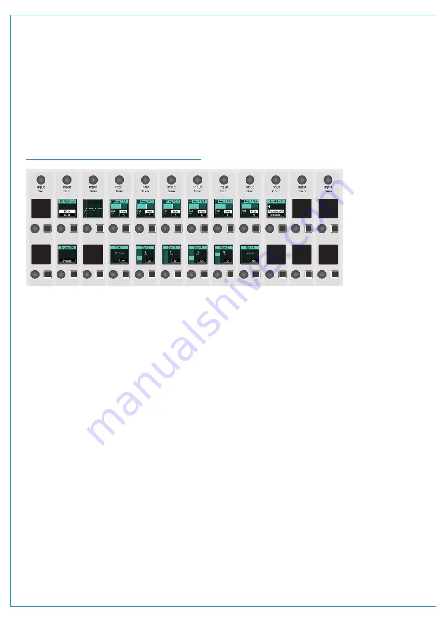
From the surface, push the ACCESS control mode button to populate the control cells with EQ and dynamics controls
for the currently accessed path. On a Summa 12+8 the control cells on the far left allow you to switch between viewing
dynamics and EQ controls. On the two larger surfaces both are always displayed. EQ controls are shown here:
FIGURE 1 -
CONTROL CELLS—ACCESS MODE—EQ
Touch Display EQ Controls
With the touch display in ‘active Show’ view tap the EQ processing tab to view controls for the currently accessed path.
Tap on any of the 6 EQ band tabs along the top of the control window to highlight that band in the EQ graph display.
The EQ controls to the right of the screen apply to whichever EQ band is currently selected. The graph instantly updates
to reflect all EQ parameter changes. Any EQ band can be set to any response type but good practice is to set them in a
logical, frequency-based order: band 1—low cut filter, up to band 6—high cut filter.
•
Each EQ band has a dedicated on/off switch.
•
Response: Select the desired EQ response curve for the selected band, from high cut filter, high shelf, notch, bell,
low shelf, low cut filter.
•
Frequency: Sets the frequency that the EQ band is operating around.
•
Gain: Sets the gain increase or reduction for the band.
•
Q: Sets the width of the frequency band for the selected response. The higher the Q, the narrower the bandwidth.
Once a response type is selected, the relevant Frequency/Gain/Q controls become active. There are several ways to
manipulate these controls:
•
Drag up and down or left or right on the touch display to turn the rotary control.
•
Drag the band node up, down, left or right within the EQ graph.
•
Tap to select the control that you wish to adjust and it is automatically assigned to the parameter adjust rotary on
the surface.
Содержание SUMMA
Страница 1: ...calrec com Putting Sound in the Picture Networked Audio Production System SUMMA USER MANUAL V3 2...
Страница 11: ...V3 0 196 V3 1 197 V3 1 1 197 V3 2 197 CALREC Putting Sound in the Picture 11...
Страница 12: ...12 SUMMA Networked Audio Production System CONTENTS...
Страница 13: ...PRODUCT INFORMATION calrec com Putting Sound in the Picture SUMMA...
Страница 20: ...20 SUMMA Networked Audio Production System PRODUCT INFORMATION...
Страница 21: ...SYSTEM OVERVIEW calrec com Putting Sound in the Picture SUMMA...
Страница 33: ...CALREC Putting Sound in the Picture 33...
Страница 38: ...38 SUMMA Networked Audio Production System SYSTEM OVERVIEW...
Страница 52: ...52 SUMMA Networked Audio Production System SYSTEM OVERVIEW...
Страница 53: ...SETTING UP calrec com Putting Sound in the Picture SUMMA...
Страница 55: ...FIGURE 1 SYNCHRONISATION OPTIONS CALREC Putting Sound in the Picture 55...
Страница 74: ...74 SUMMA Networked Audio Production System SETTING UP...
Страница 75: ...GETTING SIGNALS IN AND OUT calrec com Putting Sound in the Picture SUMMA...
Страница 78: ...FIGURE 3 FADER LAYOUT SETTINGS 78 SUMMA Networked Audio Production System GETTING SIGNALS IN AND OUT...
Страница 93: ...FIGURE 4 SOURCE AND DESTINATION POP UP MEMORY LOAD CALREC Putting Sound in the Picture 93...
Страница 98: ...FIGURE 1 THE DIRECT OUTPUT WINDOW 98 SUMMA Networked Audio Production System GETTING SIGNALS IN AND OUT...
Страница 105: ...MONITORING calrec com Putting Sound in the Picture SUMMA...
Страница 107: ...FIGURE 2 EXAMPLE LOUDSPEAKERS SETUP CALREC Putting Sound in the Picture 107...
Страница 110: ...FIGURE 1 THE MONITORING POP UP 110 SUMMA Networked Audio Production System MONITORING...
Страница 113: ...METERING calrec com Putting Sound in the Picture SUMMA...
Страница 121: ...calrec com Putting Sound in the Picture SUMMA PROCESSING...
Страница 153: ...COMMUNICATIONS calrec com Putting Sound in the Picture SUMMA...
Страница 161: ...FIGURE 4 MIX MINUS CONTRIBUTION POP UP CALREC Putting Sound in the Picture 161...
Страница 163: ...ROUTING calrec com Putting Sound in the Picture SUMMA...
Страница 165: ...FIGURE 1 CONFIGURING BUSES AND OUTPUTS CALREC Putting Sound in the Picture 165...
Страница 171: ...EXTERNAL INTERFACING calrec com Putting Sound in the Picture SUMMA...
Страница 179: ...FIGURE 2 LAN CONFIGURATION WINDOW CALREC Putting Sound in the Picture 179...
Страница 180: ...180 SUMMA Networked Audio Production System EXTERNAL INTERFACING...
Страница 181: ...CONSOLE FACILITIES calrec com Putting Sound in the Picture SUMMA...
Страница 187: ...TERMINOLOGY calrec com Putting Sound in the Picture SUMMA...
Страница 195: ...FEATURES BY SOFTWARE VERSION calrec com Putting Sound in the Picture SUMMA...


