Networked Audio Production System
User Meters
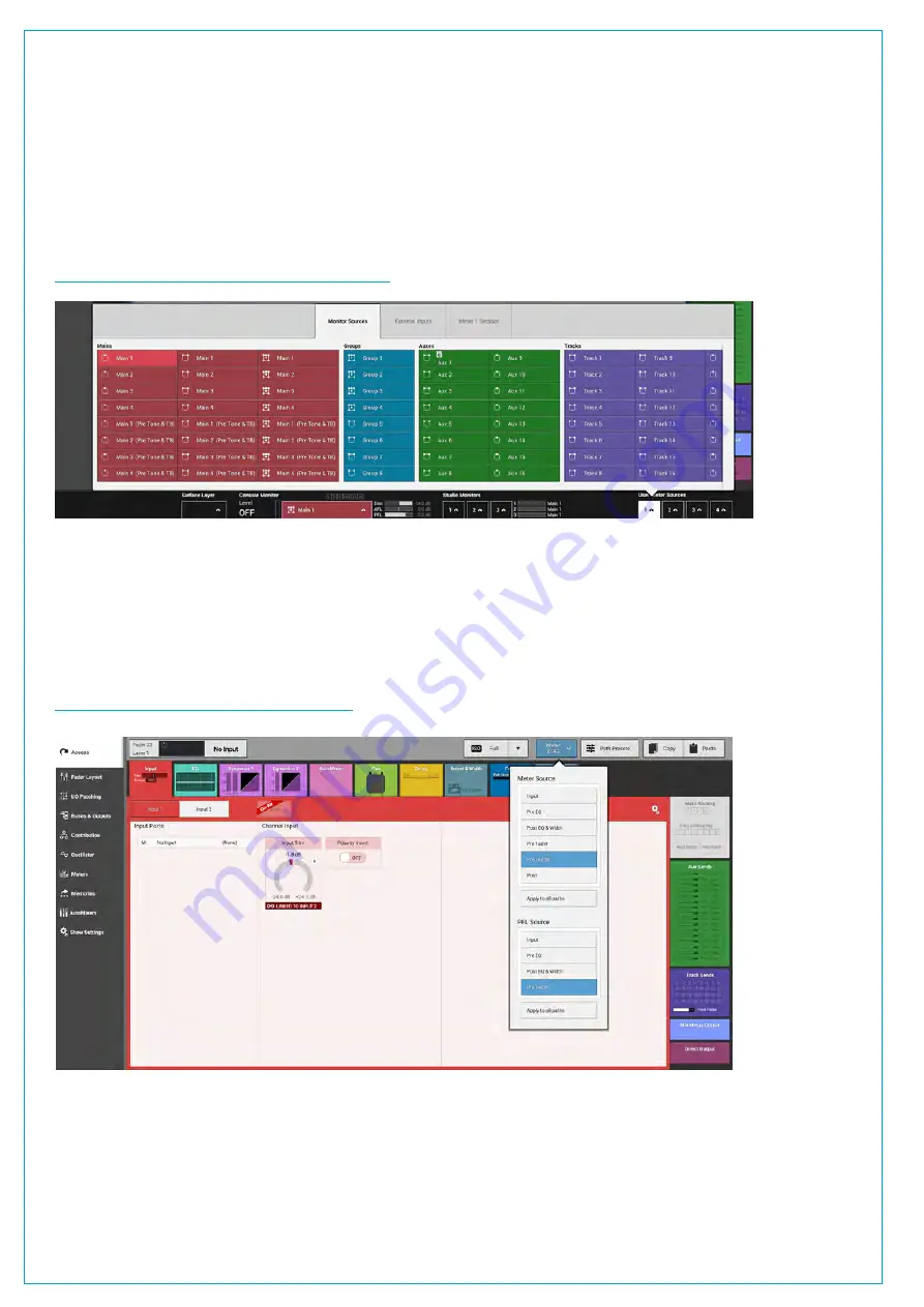
User meters 1-4 provide metering for paths which the user wishes to display. The 4 user meters are placed on the meter
bridge as part of the configurable meter layout. Any bus output can be chosen as a user meter source. User meter
sources can be selected quickly using the meter selector buttons to the bottom right of the touch display when in ‘active
Show’ view for each of the 4 user meters. The image below shows the user meter 1 selection pop-up, which follows a
similar structure to the monitor pop-up, with a source select tab, an external inputs tab and a settings tab. The sources
tab is shown here.
FIGURE 6 -
USER METER SELECTION POP-UP
Meter Position in Audio Chain
The Metering point may now be placed at the Input, Pre EQ, Post EQ, Pre Fader, Post Fader or Post which is the last
point in the Audio Path. This is accessed from the Meter & PFL button in the Screen Header. These Selections can be
made per path, or applied easily to all Paths See Figure 7 below.
FIGURE 7 -
METER POSITION SELECTOR
Содержание SUMMA
Страница 1: ...calrec com Putting Sound in the Picture Networked Audio Production System SUMMA USER MANUAL V3 2...
Страница 11: ...V3 0 196 V3 1 197 V3 1 1 197 V3 2 197 CALREC Putting Sound in the Picture 11...
Страница 12: ...12 SUMMA Networked Audio Production System CONTENTS...
Страница 13: ...PRODUCT INFORMATION calrec com Putting Sound in the Picture SUMMA...
Страница 20: ...20 SUMMA Networked Audio Production System PRODUCT INFORMATION...
Страница 21: ...SYSTEM OVERVIEW calrec com Putting Sound in the Picture SUMMA...
Страница 33: ...CALREC Putting Sound in the Picture 33...
Страница 38: ...38 SUMMA Networked Audio Production System SYSTEM OVERVIEW...
Страница 52: ...52 SUMMA Networked Audio Production System SYSTEM OVERVIEW...
Страница 53: ...SETTING UP calrec com Putting Sound in the Picture SUMMA...
Страница 55: ...FIGURE 1 SYNCHRONISATION OPTIONS CALREC Putting Sound in the Picture 55...
Страница 74: ...74 SUMMA Networked Audio Production System SETTING UP...
Страница 75: ...GETTING SIGNALS IN AND OUT calrec com Putting Sound in the Picture SUMMA...
Страница 78: ...FIGURE 3 FADER LAYOUT SETTINGS 78 SUMMA Networked Audio Production System GETTING SIGNALS IN AND OUT...
Страница 93: ...FIGURE 4 SOURCE AND DESTINATION POP UP MEMORY LOAD CALREC Putting Sound in the Picture 93...
Страница 98: ...FIGURE 1 THE DIRECT OUTPUT WINDOW 98 SUMMA Networked Audio Production System GETTING SIGNALS IN AND OUT...
Страница 105: ...MONITORING calrec com Putting Sound in the Picture SUMMA...
Страница 107: ...FIGURE 2 EXAMPLE LOUDSPEAKERS SETUP CALREC Putting Sound in the Picture 107...
Страница 110: ...FIGURE 1 THE MONITORING POP UP 110 SUMMA Networked Audio Production System MONITORING...
Страница 113: ...METERING calrec com Putting Sound in the Picture SUMMA...
Страница 121: ...calrec com Putting Sound in the Picture SUMMA PROCESSING...
Страница 153: ...COMMUNICATIONS calrec com Putting Sound in the Picture SUMMA...
Страница 161: ...FIGURE 4 MIX MINUS CONTRIBUTION POP UP CALREC Putting Sound in the Picture 161...
Страница 163: ...ROUTING calrec com Putting Sound in the Picture SUMMA...
Страница 165: ...FIGURE 1 CONFIGURING BUSES AND OUTPUTS CALREC Putting Sound in the Picture 165...
Страница 171: ...EXTERNAL INTERFACING calrec com Putting Sound in the Picture SUMMA...
Страница 179: ...FIGURE 2 LAN CONFIGURATION WINDOW CALREC Putting Sound in the Picture 179...
Страница 180: ...180 SUMMA Networked Audio Production System EXTERNAL INTERFACING...
Страница 181: ...CONSOLE FACILITIES calrec com Putting Sound in the Picture SUMMA...
Страница 187: ...TERMINOLOGY calrec com Putting Sound in the Picture SUMMA...
Страница 195: ...FEATURES BY SOFTWARE VERSION calrec com Putting Sound in the Picture SUMMA...


