Appendix D: Micro-CS Upgrade Installation
D-6
Micro-CS Installation Guide
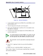
Figure D-4
: Micro-CS Installation
6.
Connect the RJ45 cable from the EPIM-3PS (or the BRIM) to the J3
jack on the Micro-CS.
7.
Check the alignment of the ports on the front panel.
8.
Insert screws through holes in the Micro-CS to the standoffs in the
MicroMMAC and tighten.
9.
Locate the mylar replacement faceplate for the MicroMMAC and
carefully attach it now.
10.
Attach FCC Compliance Label to the rear of the MicroMMAC
chassis.
11.
Replace the cover on the MicroMMAC, and apply power.
Please return to Chapter 2 for information regarding Setup, Commands,
and Software Installation.
TIP
The mylar faceplate for the MicroMMAC is very sticky. You may
only have one chance to get it on right. It is easier if you start
from the right side of the MicroMMAC and align the corners.
Ensure that the cover is in place before connecting the power
cord.
J3
Содержание MICRO-CS
Страница 2: ......
Страница 8: ...vi Micro CS Installation Guide...
Страница 12: ...Contents iv Micro CS Installation Guide...
Страница 22: ...Chapter 1 Introduction 1 10 Micro CS Installation Guide...
Страница 32: ...Chapter 2 Micro CS Installation 2 10 Micro CS Installation Guide...
Страница 72: ...Chapter 4 Troubleshooting Procedures 4 14 Micro CS Installation Guide...
Страница 82: ...Appendix C Flash Upgrade Instructions C 4 Micro CS Installation Guide...
Страница 92: ...Index 4 Micro CS Installation Guide...


