Appendix A: Port Pin/Signal Allocations
A-2
Micro-CS Installation Guide
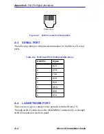
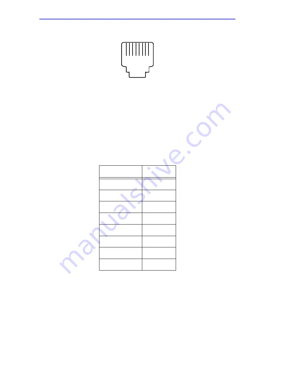
Figure A-1
RJ45 Console Port Receptacle
A.3
SERIAL PORT
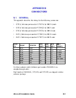
The following table provides pinout information for the Micro-CS serial
ports.
A.4
LAN NETWORK PORT
There are two ways to connect to the network with the Micro-CS:
Through an RJ45 connector to the MicroMMAC internal AUI, or through
an RJ45 mounted on the front panel.
Table A-2
RJ45 Serial Port Pin/Signal Allocations
RJ45 Pin
Signal
1
RTS
2
DTR
3
TXD
4
DCD
5
RXD
6
GND
7
DSR
8
CTS
1
8
Front view
Содержание MICRO-CS
Страница 2: ......
Страница 8: ...vi Micro CS Installation Guide...
Страница 12: ...Contents iv Micro CS Installation Guide...
Страница 22: ...Chapter 1 Introduction 1 10 Micro CS Installation Guide...
Страница 32: ...Chapter 2 Micro CS Installation 2 10 Micro CS Installation Guide...
Страница 72: ...Chapter 4 Troubleshooting Procedures 4 14 Micro CS Installation Guide...
Страница 82: ...Appendix C Flash Upgrade Instructions C 4 Micro CS Installation Guide...
Страница 92: ...Index 4 Micro CS Installation Guide...

