background image

Chapter 3: ROM Monitor Commands

3-24

Micro-CS Installation Guide

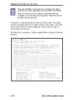
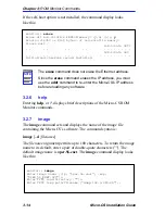
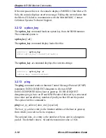
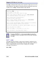
The slip command automatically sets the number of data bits to 8 for all 
SLIP interfaces. The number of data bits does not include the start, stop, 
or parity bits. The slip command display looks like this:

3.2.17

stats

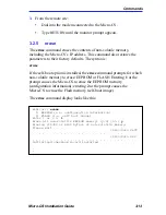
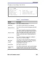
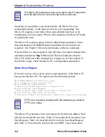
The stats command displays current network statistics gathered by the 
ROM. Use stats along with the boot command to help isolate problems. 
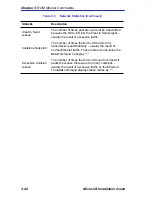
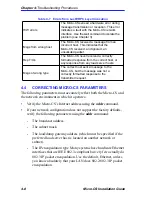
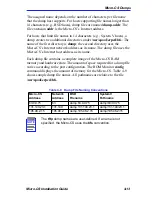
Table 3-3 describes the network statistics displayed by the stats 
command. The syntax is:

stats [-slip]

NOTE

Pressing


interrupts the slip command; the 

parameters remain unchanged until the command completes 
normally.

monitor:: slip

Line number (1-16):: 6

Allow SL/IP on this port? (y/n) [n]:: y

Local endpoint address: 192.9.200.214

Enter subnet mask [255.255.255.0]::

Enter remote endpoint address [0.0.0.0.]:: 192.9.200.0
Remote endpoint address: 192.9.200.0

Enter remote load/dump host address [default 192.9.200.88]::
Using remote endpoint address: 192.9.200.88


Enter local endpoint address [0.0.0.0]:: 192.9.200.214


Constructed new subnet mask.

Should this interface be used for memory dumps? (y/n) [y]::

Enter the baud rate [9600]::

Enter the number of stop bits (1,1.5,2) [1]::

Enter the parity (none,even,odd) [none]::

Содержание MICRO-CS

Страница 1: ...11X 10X 9X 8X 7X 6X 5X 4X 3X 2X 1X 12 11 10 9 8 7 6 5 4 3 2 1 COM 2 COM 1 RESET DISPLAY SETUP 7 6 5 4 3 2 ETHERNET MODEM 1 7 6 5 4 3 2 1 M INT TXD RXD DTR CTS DCD ATTN STATUS SETUP NET PORT Micro CS...

Страница 2: ......

Страница 3: ...MS HAS BEEN ADVISED OF KNOWN OR SHOULD HAVE KNOWN THE POSSIBILITY OF SUCH DAMAGES Copyright April 1997 by Cabletron Systems Inc P O Box 5005 Rochester NH 03866 5005 All Rights Reserved Printed in the...

Страница 4: ...es and can radiate radio frequency energy and if not installed in accordance with the operator s manual may cause harmful interference to radio communications Operation of this equipment in a resident...

Страница 5: ...tified equipment should be made by an authorized Canadian maintenance facility designated by the supplier Any repairs or alterations made by the user to this equipment or equipment malfunctions may gi...

Страница 6: ...THAN THOSE SUPPLIED TO YOU BY CABLETRON IN WRITING EITHER EXPRESS OR IMPLIED INCLUDING BUT NOT LIMITED TO IMPLIED WARRANTIES OF MERCHANTABLITY AND FITNESS FOR A PARTICULAR PURPOSE WITH RESPECT TO THE...

Страница 7: ...INSTRUCTIONS AND OR EQUIPMENT MANUFACTURER TO VERIFY CONFIRM YOUR EQUIPMENT IS SUITABLE FOR INSTALLED APPLICATION CARDS CAUTION ALWAYS DISCONNECT MODEM BOARD THE ONE WITH THE TELEPHONE PLUG JACK FROM...

Страница 8: ...vi Micro CS Installation Guide...

Страница 9: ...System Status LEDs 1 6 1 5 7 Modem Status LEDs 1 7 1 5 8 SETUP Switch 1 7 1 5 9 Port Activity Indicators 1 7 1 5 10 Console Port 1 8 1 5 11 Network Port 1 8 1 5 12 Modem Port 1 8 1 6 Micro CS Physical...

Страница 10: ...14 ports 3 19 3 2 15 sequence 3 21 3 2 16 slip 3 22 3 2 17 stats 3 24 CHAPTER 4 TROUBLESHOOTING PROCEDURES 4 1 General 4 1 4 2 Power Up and Boot Procedures 4 1 4 2 1 Normal Mode 4 1 4 3 Boot Failures...

Страница 11: ...3 Required Tools C 1 C 4 Installation Procedure C 2 C 4 1 Installing the Flash Daughter Card C 2 C 4 2 Changing the Boot Method C 3 APPENDIX D MICRO CS UPGRADE INSTALLATION D 1 General D 1 D 2 Locatin...

Страница 12: ...Contents iv Micro CS Installation Guide...

Страница 13: ...requirements network guidelines getting help and operating specifications Chapter 2 Micro CS Installation contains instructions for network connections attaching to the ports power up and test informa...

Страница 14: ...special importance CAUTION Caution symbol Contains information essential to avoid damage to the equipment Electrical Hazard Warning symbol Warns against an action that could result in personal injury...

Страница 15: ...is this a recurring problem etc Any previous Return Material Authorization RMA numbers 1 5 MICRO CS OVERVIEW The Cabletron Micro CS is a Xylogics Remote Annex 2000 compatible multi port communication...

Страница 16: ...Using the ROM Monitor commands you can Modify and display a set of EEPROM parameters Execute interactive diagnostic tests Receive information and statistics for the hardware configuration and the netw...

Страница 17: ...e Micro CS Figure 1 1 front panel contains the following 4 System Indicators 5 Modem status indicators Modem port indicator when optional modem is operating 7 port LEDs Internal connection indicator S...

Страница 18: ...UP and ATTN LED s will be on when the Micro CS is in Monitor mode ATTN amber On when the Micro CS requires operator attention Flashing when the unit encounters a problem STATUS green On when the unit...

Страница 19: ...ators associated with ports 1 7 blink to indicate data either data transmitted to or received by that port The M port lights to indicate the modem is seeing activity The 5 modem LED s blink to indicat...

Страница 20: ...45 connector on the front panel between the network port and a port on the MicroMMAC The internal AUI is provided by the Cabletron EPIM 3PS provided with the Micro CS The Micro CS automatically sets...

Страница 21: ...VIRONMENT Operating 5 to 40 C 41 to 104 F 5 to 90 relative humidity non condensing Storage 30 to 73 C 22 to 164 F 1 8 APPROVALS Safety This equipment meets the safety requirements of UL 1950 CSA C22 2...

Страница 22: ...Chapter 1 Introduction 1 10 Micro CS Installation Guide...

Страница 23: ...lease refer to the MicroMMAC documentation This chapter explains the connection of serial devices attaching to the console port power up and testing and software installation of your new Micro CS Plea...

Страница 24: ...ons Port 1 is used for the initial console connection but reverts to an Annex serial port after bootup To connect to serial devices simply insert one end of the RJ45 cable into one of the seven number...

Страница 25: ...t the Micro CS and enter the ROM Monitor mode by pressing the SETUP switch for at least three seconds until the SETUP LED flashes indicating a reset Release the switch and all the port LEDs will turn...

Страница 26: ...hin one minute or if the indicators flash a hardware failure has occurred Contact Cabletron Technical Support 4 Verify the Micro CS hardware configuration At the monitor prompt on the console type con...

Страница 27: ...assed If it fails an error message is displayed 7 Ping the software load host as well as the IP address of the MicroMMAC This will test the connectivity of the Micro CS to a remote device NOTE You are...

Страница 28: ...on Protocol maps a hardware address into an Internet address The ROMs invoke this system of acquiring boot information when a boot is initiated and the Micro CS s Internet Address is not initialized U...

Страница 29: ...pd should respond to the client Micro CS in this case with whatever format the client requests the Micro CS client always requests in the decimal dot notation format 99 130 83 99 The bootpd adds the a...

Страница 30: ...be installed from a UNIX host on a network To do this the operational code must first be loaded on the UNIX host The Micro CS may also be booted from software loaded on a another Micro CS or from Fla...

Страница 31: ...quence command to list the SLIP network interface in the load dump interface list see the sequence command in Chapter 3 4 Execute the boot command see the boot command in Chapter 3 After successful ex...

Страница 32: ...Chapter 2 Micro CS Installation 2 10 Micro CS Installation Guide...

Страница 33: ...ts minimizes errors during the initial boot For example setting the parameter that defines the preferred load host enables the Micro CS to load by requesting assistance from a specific host rather tha...

Страница 34: ...aud rate erase Erases non volatile memory help or Display the list of ROM Monitor commands image d file Displays and or sets the load image and TFTP load dump names ipx d Sets IPX load dump file serve...

Страница 35: ...t The addr d command also displays the unit s ROM resident Ethernet address in hexadecimal notation see the CSMIM MicroCS Administrator s Guide for UNIX The command syntax is addr d If you enter the a...

Страница 36: ...st address 192 9 200 88 Enter Preferred Dump Host address 0 0 0 0 192 9 200 88 Preferred Dump Host address 192 9 200 88 Enter Load Dump Gateway address uninitialized 192 9 200 Load Dump Gateway addres...

Страница 37: ...at host must be reached through a gateway The addr command prompts you for this gateway s IP address The Micro CS uses the broadcast address parameter when loading a file If this parameter contains a...

Страница 38: ...t message to the selected host After receiving a response the Micro CS loads its operational code to RAM memory When loading is complete it transfers control to the newly loaded program The Micro CS d...

Страница 39: ...us word XXXX where XXXX are four hexadecimal digits decodes as follows 8000 Command complete 4000 Chip is busy 2000 Command completed without error 1000 Command aborted by an abort command 800 Late co...

Страница 40: ...equests shown as transmission errors as Requesting boot from 192 9 200 88 via Ethernet Booting BFS file using open delay of 8 Booting BFS file from 192 9 200 88 Header received OK Received data blocks...

Страница 41: ...show the newly loaded image monitor boot l Enter boot file name ip oper 56 enet mop OPER_56_ENET SYS Requesting default boot file OPER_56_ENET SYS for MOP VMS loads and oper 56 enet for all other prot...

Страница 42: ...nanswered requests shown as transmission errors as Requesting boot from 192 9 200 88 via Ethernet Booting from 192 9 200 88 42 msec Header received OK Received data blocks shown as msec turnaround tim...

Страница 43: ...ommand changes the console port s baud rate Thus the console port can interface with any modem to which it is connected When the baud rate is entered as auto the Micro CS detects the baud rate of the...

Страница 44: ...TE This command has no effect on the port s baud rate after the Micro CS is booted monitor console baud Remote Diagnostic Test Mode In order to use the remote diagnostic functionality you must first c...

Страница 45: ...talled the erase command prompts for which non volatile memory to erase EEPROM or FLASH Entering 1 at the prompt causes the Micro CS to erase the EEPROM memory configuration information entering 2 at...

Страница 46: ...ts default enter a pair of double quote characters The default image name is oper 56 enet The image command display looks like this NOTE The erase command does not erase the Ethernet address Since the...

Страница 47: ...the self boot image is loaded If the image file name contains more than 16 characters it is truncated when MOP is attempted monitor image d Image name Default ip oper 56 enet Default mop OPER_56_ENET...

Страница 48: ...onitor The command syntax is lat_key d The lat_key command display looks like this The lat_key d command displays the current LAT key setting NOTE The lat_key command is optional and may be purchased...

Страница 49: ...t transceiver loopback test on the local area network The command syntax is net The net command display looks like this This transciever loopback test sends out a short test packet from the Micro CS t...

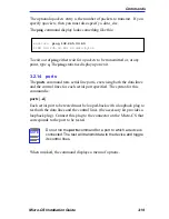
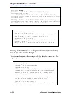
Страница 50: ...3 2 13 ping The ping command sends an Internet Control Message Protocol ICMP mandatory ECHO_REQUEST datagram to elicit an ICMP ECHO_RESPONSE from a host or gateway ECHO_REQUEST datagrams pings have an...

Страница 51: ...data lines and the control lines for each serial port specified The syntax for this command is ports d Each serial port to be tested must be looped back with a loopback plug to test both the data lin...

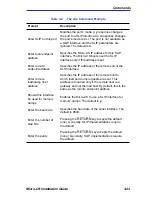
Страница 52: ...ith faulty Control Lines Ports with faulty Data Lines Enter port number or range of ports to test Return to exit 3 Enter the number of times to loop on this test 1 Testing data lines on channel 3 ERRO...

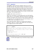
Страница 53: ...n where nn is a port number and specify self boot by selecting self Separate each interface with a comma or a space Enter the interface list as an argument to the command otherwise the console display...

Страница 54: ...s the port number 3 2 16 slip The slip command defines a serial port as a Serial Line Internet Protocol SLIP interface This command defines a number of port parameters The command syntax is slip d por...

Страница 55: ...remote end of the SLIP interface Enter remote load dump host address Specifies the IP address of the remote host to which load and dump requests are sent This address is required only if the remote h...

Страница 56: ...yntax is stats slip NOTE Pressing CONTROL C interrupts the slip command the parameters remain unchanged until the command completes normally monitor slip Line number 1 16 6 Allow SL IP on this port y...

Страница 57: ...e normal Bus Wait Drops The number of packets dropped due to waiting too long for a bus to become available Bad Types Lengths The number of unknown packet types if Ethernet IP encapsulation is being u...

Страница 58: ...mber of times the Micro CS had to retry transmissions automatically usually the result of normal Ethernet traffic These retries do not cause the boot command to display Excessive Collision Losses The...

Страница 59: ...rogress report and an error display to assist you in troubleshooting 4 2 POWER UP AND BOOT PROCEDURES The Micro CS has two modes of operation normal and SETUP Normal mode is the standard operational m...

Страница 60: ...se diagnostics test internal hardware functions If a test fails the ATTN and STATUS LEDs flash and an error message is displayed if the console port is selected The NET indicator flashes during the po...

Страница 61: ...rrors occur Configuring the Micro CS with an incorrect file name or renaming or copying the image file to the wrong name Supplying the wrong name to any of the boot commands na boot dumpboot or the su...

Страница 62: ...mode Press the SETUP switch to put the Micro CS into monitor mode Activity T2 Testing the Hardware During power up the Micro CS runs self tests that execute CPU diagnostics ROM and E2 PROM flash check...

Страница 63: ...loaded an inappropriate image Pressing the SETUP switch approximately 3 seconds to generate a reset clears this error The Micro CS loads inappropriate images if one of the following operator errors o...

Страница 64: ...configuration parameters Boot Error Report If an error occurs a boot error report is generated only if the Micro CS has opened the boot file The report uses the following format BOOT ERROR REPORT for...

Страница 65: ...from the port Table 4 5 Errors from Last Open Request ARP errors Address Resolution Protocol ARP errors indicate that the Micro CS is configured to boot from a specified host but the host would not tr...

Страница 66: ...ompliant but very few actually do 802 3 IP packet encapsulation Use the default Ethernet unless you know absolutely that your LAN does 802 2 802 3 IP packet encapsulation Table 4 7 Errors from Last ER...

Страница 67: ...correct the Micro CS cannot boot Correct the name using the image command If the address for the preferred load server host is incorrect the boot takes longer since the Micro CS has to broadcast for a...

Страница 68: ...Micro CS into SETUP mode press the SETUP switch after a reset and wait for monitor prompt To place erpcd on the load server host into test mode kill the erpcd program requires superuser privileges and...

Страница 69: ...ided with the distribution and installed in the file etc running in the background on the PC Set the Micro CS and the erpcd on the load host into Set Up mode For the Micro CS press SETUP following a r...

Страница 70: ...igger Micro CS dumps are Non recoverable hardware or software errors Software fails to reset the Micro CS s watchdog timer Software fails one or more internal consistency checks Hardware detects an in...

Страница 71: ...le uses the Micro CS s Internet host address as its name Each dump file contains a complete image of the Micro CS RAM memory and hardware state The amount of space required for a dump file varies acco...

Страница 72: ...Chapter 4 Troubleshooting Procedures 4 14 Micro CS Installation Guide...

Страница 73: ...ONSOLE PORT When the Micro CS is in SETUP mode port 1 becomes the console port The cable shipped with the Annex Communication Software can be used as the console cable NOTE Port 1 of the Micro CS serv...

Страница 74: ...ut information for the Micro CS serial ports A 4 LAN NETWORK PORT There are two ways to connect to the network with the Micro CS Through an RJ45 connector to the MicroMMAC internal AUI or through an R...

Страница 75: ...UI RJ45 Pin Signal Direction Signal Type 1 DI IN Data 2 DI IN Data 3 DO OUT Data 4 DO OUT Data 5 CI IN Collision 6 CI IN Collision 7 LINKUP IN Control 8 LINKDN OUT Control Table A 4 Front Panel 10BASE...

Страница 76: ...Appendix A Port Pin Signal Allocations A 4 Micro CS Installation Guide 3 Tip 4 A1 Table A 5 Modem Port Pinouts RJ11 Pin Signal...

Страница 77: ...abletron part number 9372083 for DB25 female DCE Cabletron part number 9372075 for DB25 male Use these adapters with Cabletron part number 9360005 X or a straight through cable Part Numbers 9360005 X...

Страница 78: ...nstallation Guide B 2 ADDITIONAL CABLETRON CABLES AND CONNECTORS Micro CS to Micro CS Rollover Cable part number 9360167 XX Micro CS to RJ45 Console Connector part number 9360166 XX Micro CS to DB9 Co...

Страница 79: ...ng Kit contents Required tools Installation instructions C 2 CONTENTS OF THE KIT Table C 1 lists the contents of the Micro CS upgrade kit C 3 REQUIRED TOOLS The only required tool is a Phillips screwd...

Страница 80: ...nsuring that the nylon standoffs snap into their mating holes on the board Figure C 1 Flash Card Installation Please note that although the hardware configuration of the FLASH card is the same for the...

Страница 81: ...At this prompt enter self cr 6 Now check for a bootable image in the flash PROM At the monitor prompt enter image d cr 7 The last line of the response should read SELF image name oper 52 enet 8 If th...

Страница 82: ...Appendix C Flash Upgrade Instructions C 4 Micro CS Installation Guide...

Страница 83: ...o a MicroMMAC See the appropriate appendices for the installation of additional memory and or Flash upgrades After completing the physical installation please return to Chapter 2 for setup information...

Страница 84: ...resent DO NOT use jumper J18 1 2 Installed SIMMs are 4Mx8 2 3 Installed SIMMs are 1Mx8 OR if no SIMMS are present J25 1 2 Modem uses ROM for configuration data The modem uses Power On and ATZ Reset So...

Страница 85: ...oved in order to facilitate installation of the Micro CS CAUTION Observe all antistatic precautions when handling electronic components Table 4 2 Micro CS Upgrade Kit Contents Item Qty Description Par...

Страница 86: ...have to remove certain components at this time 2 Remove the upper port cutout blank or the 12 port daughter card from the MicroMMAC Ensure that the power cord is removed from the unit before removing...

Страница 87: ...rboard there are four screws see Figure D 3 b For the MicroMMAC 22E you will have to remove the two screws on either side of JP2 and replace with 1 standoffs 3 Install the EPIM 3PS with the RJ45 cable...

Страница 88: ...mylar replacement faceplate for the MicroMMAC and carefully attach it now 10 Attach FCC Compliance Label to the rear of the MicroMMAC chassis 11 Replace the cover on the MicroMMAC and apply power Ple...

Страница 89: ...ting CSMIM to console 2 1 to serial devices 2 2 Console Port A 1 Console port description of 1 8 console port 1 8 2 1 Console terminal description 2 1 console baud command 3 11 D dumps 4 12 files 4 12...

Страница 90: ...A 1 port upgrade instructions 2 1 C 1 ports command 3 19 power up applying power 2 3 failures during 2 4 in normal mode 4 1 in SETUP mode 4 3 instructions 2 3 running self tests 2 4 self testing proc...

Страница 91: ...command 3 24 example 3 25 status indicators description of 1 7 subnet mask setting 3 5 System Description 1 4 T test Ethernet transceiver loopback 3 17 printer port 3 19 serial line ports 3 19 test mo...

Страница 92: ...Index 4 Micro CS Installation Guide...

Страница 93: ...die Anwendung des Geraetes geeignet und der zum Benuetzen im Lande der Anwendung anerkannt ist SPANISH El cable principal de la red el ctrica utilizado con este equipo debe tener 2 conductores y 1 to...

Отзывы: