


5. POWER SUPPLY EQUIPMENT
RH-981A
81
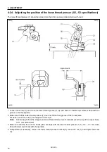
5-2-1. Before replacing a fuse
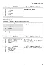
If fuse No.1 is blown
1. Separate connectors P5 (DC300) on the power
supply circuit board, and measure the resistance with
the polarities as shown in the figure.
If the resistance is 0 ohms (it means a short-circuit),
replace the power supply circuit board.
2. Separate connectors P1 (POWER) on the power
supply circuit board, and measure the resistance
between pins 4 and 7 on the board with the polarities
as shown in the figure.
If the resistance is 0 ohms (it means a short-circuit),
replace the power supply circuit board.
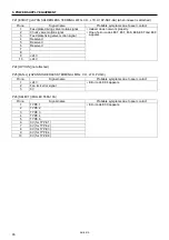
If fuse No.2 is blown
Separate connectors P15 (DC300) on the control circuit
board, and measure the resistance between pins 1 and
2 on the board with the polarities as shown in the figure.
If the resistance is 0 ohms (it means a short-circuit),
replace the power supply circuit board.
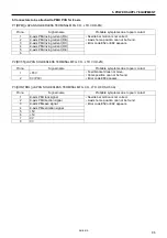
If fuse No.3 or 4 is blown
Separate connectors P1 (ACIN) on the power supply
circuit board, and measure the resistance of the three
places between A and B, A and C, and B and C on the
board with the polarities as shown in the figure.
If the resistance is 0 ohms (it means a short-circuit), or
the resistance between A and C or B and C is not infinity,
replace the power supply circuit board.
3522Q
BLACK
BLACK
RED
3523Q
3524Q
RED
BLACK
3525Q
RED
Содержание RH-981A
Страница 8: ...RH 981A ...
Страница 23: ...2 DISASSEMBLY RH 981A 15 2 7 Needle bar thread take up and zigzag mechanisms 3710Q 3711Q 3709Q 3708Q ...
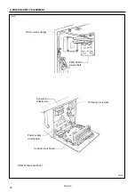
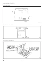
Страница 92: ...5 POWER SUPPLY EQUIPMENT RH 981A 84 Control circuit board Power supply circuit board 3530Q 3531Q ...
Страница 119: ...6 AIR PRESSURE MECHANISM RH 981A 111 5 Cloth opener cylinder 6 Lower thread trimming cylinder 3554Q 3555Q ...
Страница 136: ...7 SOFTWARE RH 981A 128 7 6 Control circuit block diagram 1 3842Q ...
Страница 137: ...7 SOFTWARE RH 981A 129 7 7 Control circuit block diagram 2 3843Q ...
Страница 138: ...SERVICE MANUAL Printed in Japan RH 981A I3080846H 2003 10 H 1 http www brother com ...


