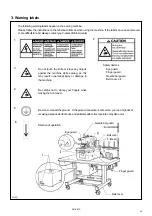


RH-981A
4-12. Adjusting the height of the spreader
and looper..........................................................56
4-13. Adjusting the needle and looper timing............57
4-14. Adjusting the loop stroke ..................................58
4-15. Adjusting the height of the needle bar .............59
4-16. Adjusting the clearance between
the looper and needle .......................................59
4-17. Adjusting the needle guard...............................60
4-18. Adjusting the spreader mounting positions .....60
4-19. Adjusting the spreader timing...........................61
4-20. Adjusting the amount to pull
the upper thread and tension release ..............61
4-21. Adjusting upper thread trimming ......................62
4-21-1. Adjusting the upper movable
knife mounting position..............................62
4-21-2. Adjusting the position of the thread
trimmer lever bracket.................................63
4-22. Adjusting the lower thread trimmer
(-01 specification).............................................63
4-22-1.Adjusting the knife pressure ......................63
4-22-2.Adjusting the position of the
thread trimmer arm ....................................64
4-22-3.Adjusting the thread clamp assembly
and thread clamp opener...........................65
4-22-4.Adjusting the thread handler .....................66
4-22-5.Adjusting the thread guide plate................67
4-22-6.Adjusting the amount to pull the lower
thread required for thread trimming ..........67
4-22-7.Adjusting the amount to pull the lower
thread for safety stitching...........................68
4-22-8.Adjusting the amount to pull the gimp.......68
4-23. Adjusting the lower thread trimmer
(-02, -52 specifications).....................................69
4-23-1. Adjusting the knife engagement ...............69
4-23-2. Adjusting the knife pressure......................70
4-23-3. Adjusting the gimp pull force .....................70
4-23-4. Adjusting the gimp tension ........................71
4-23-5. Using gimp thread work clamp .................72
4-23-6. Adjusting the auxiliary clamp arm .............73
4-23-7. Adjusting the length of the lower thread
to be pulled for a safe sewing start...........74
4-24. Adjusting the position of the lower thread presser
(-02, -52 specifications) .....................................75
4-25. Adjusting the rotating centers
of the needle bar and the looper base .............76
4-26. Adjusting the needle bar stop position.............77
5. POWER SUPPLY EQUIPMENT
.................. 78
5-1. Components inside the control box ................. 78
5-2. Fuse explanation .............................................. 80
5-2-1.Before replacing a fuse ............................... 81
5-3. Connectors........................................................ 82
5-3-1.Connector positions..................................... 82
5-3-2.Signal names for connectors and probable
symptoms due to poor contact ................... 86
5-4. Specification harness connections .................. 97
5-5. Summary of DIP switches................................ 98
5-5-1.Panel DIP switches ..................................... 98
5-5-2. Circuit board DIP switches ......................... 99
5-6. CHANGING FUNCTIONS USING
THE MEMORY SWITCHES.......................... 101
5-6-1. Memory switch table................................. 102
5-7. Sensors positions and funstions.................... 103
6. AIR PRESSURE MECHANISM
.................. 107
6-1. Solenoid valves and air tubes........................ 107
6-1-1.Adjusting the solenoid valve speed
controllers....................................................107
6-1-2.Air tubes ..................................................... 108
6-2. Air tube layout................................................. 109
7. SOFTWARE
.........................................................112
7-1. Motion flowchart.............................................. 112
7-2. Input check list ................................................ 113
7-3. Output check list ............................................. 116
7-4. List of error codes........................................... 118
7-5. Troubleshooting.............................................. 121
7-6. Control circuit block diagram (1) .................... 128
7-7. Control circuit block diagram (2) .................... 129
Содержание RH-981A
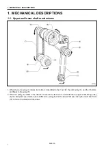
Страница 8: ...RH 981A ...
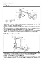
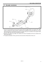
Страница 23: ...2 DISASSEMBLY RH 981A 15 2 7 Needle bar thread take up and zigzag mechanisms 3710Q 3711Q 3709Q 3708Q ...
Страница 92: ...5 POWER SUPPLY EQUIPMENT RH 981A 84 Control circuit board Power supply circuit board 3530Q 3531Q ...
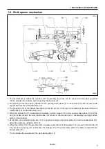
Страница 119: ...6 AIR PRESSURE MECHANISM RH 981A 111 5 Cloth opener cylinder 6 Lower thread trimming cylinder 3554Q 3555Q ...
Страница 136: ...7 SOFTWARE RH 981A 128 7 6 Control circuit block diagram 1 3842Q ...
Страница 137: ...7 SOFTWARE RH 981A 129 7 7 Control circuit block diagram 2 3843Q ...
Страница 138: ...SERVICE MANUAL Printed in Japan RH 981A I3080846H 2003 10 H 1 http www brother com ...


