


7. SOFTWARE
RH-981A
122
Code
Countermeasure
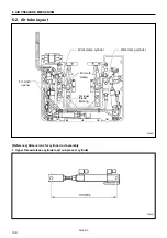
E-05
E-35
1. Check whether the air pressure is insufficient.
2. Check if the circuit board DIP switch No.3 is set to ON.
* If you are not using the pressure sensor, an error will occur if this DIP switch is set to ON.
3. Check if pins 10 and 11 of the connector P1 (ORG) on the control circuit board is securely inserted.
E-06
E-36
E-66
1. Turn on the feed plate home position sensor (limit switch R) of the indexer. (Place the cloth feed bar
at the left position.)
2. Check and adjust the position of the feed plate home position sensor of the indexer. (Refer to the
instruction manual.)
3. Of connectors relayed to head harness, check if the harness for the feed plate home position sensor
is correctly attached to the connector for the
θ
-axis home position sensor. (The white harness should
be attached to pin 7, and the black one to pin 12. Refer to the instruction manual.)
* Check if there is a harness in the control box that is broken or short-circuited.
4. Check if connector P9 (EXINB) on the control circuit board is securely inserted and if any harness is
broken or short-circuited.
5. With the power turned off, separate connectors P9 (EXINB), and check if continuity between pins 10
and 11 in the connector on the harnesses is as follows:
• When feed plate home position sensor is activated, between pins 10 and 11 is short-circuited.
• When feed plate home position sensor is not activated, between pins 10 and 11 is opened.
* If the result of continuity test is not acceptable in either case, replace the feed plate home position
sensor and its harness.
* Even if the result of continuity test is acceptable, harness may be broken or short-circuited. It may
appear when oscillation occurs.
6. If there is still an error even after replacing the feed plate home position sensor and the sensor relay
cord (attached to the control circuit board and the relay connector), replace the control circuit board.
E-07
E-37
E-67
1. Make sure that the valve unit of the indexer is supplied with air or wiring is correct.
2. Check and adjust the position of the left driving sensor (limit switch L) of the indexer. (Refer to the
instruction manual.)
3. Of connectors relayed to head harness, check if the harness for the feed plate home position sensor
is correctly attached to the connector for the
θ
-axis home position sensor. (The white harness should
be attached to pin 10, and the black one to pin 15. Refer to the instruction manual.)
* Check if there is a harness in the control box that is broken or short-circuited.
4. Check if connector P9 (EXINB) on the control circuit board is securely inserted and if any harness is
broken or short-circuited.
5. With the power turned off, separate connectors P9 (EXINB), and check if continuity between pins 1
and 2 in the connector on the harnesses is as follows:
• When left driving sensor is activated, between pins 1 and 2 is short-circuited.
• When left driving sensor is not activated, between pins 1 and 2 is opened.
* If the result of continuity test is not acceptable in either case, replace the left driving sensor and its
harness.
* Even if the result of continuity test is acceptable, harness may be broken or short-circuited. It may
appear when oscillation occurs.
6. If there is still an error even after replacing the left driving sensor and the sensor relay cord (attached
to the control circuit board and the relay connector), replace the control circuit board.
E-09
1. Connect the specification harness that conforms to machine’s specification.
2. Check if all pins are inserted into the connector of the specification harness.
3. Check if the connector for the specification harness which is outside the control box is securely
inserted.
4. Check if connector P4 (TYPE) on the control circuit board is securely inserted and if any harness is
broken or short-circuited.
5. Replace the type cord (harness connected to control circuit board and the control box).
6. Replace the control circuit board with a new one.
Содержание RH-981A
Страница 8: ...RH 981A ...
Страница 23: ...2 DISASSEMBLY RH 981A 15 2 7 Needle bar thread take up and zigzag mechanisms 3710Q 3711Q 3709Q 3708Q ...
Страница 92: ...5 POWER SUPPLY EQUIPMENT RH 981A 84 Control circuit board Power supply circuit board 3530Q 3531Q ...
Страница 119: ...6 AIR PRESSURE MECHANISM RH 981A 111 5 Cloth opener cylinder 6 Lower thread trimming cylinder 3554Q 3555Q ...
Страница 136: ...7 SOFTWARE RH 981A 128 7 6 Control circuit block diagram 1 3842Q ...
Страница 137: ...7 SOFTWARE RH 981A 129 7 7 Control circuit block diagram 2 3843Q ...
Страница 138: ...SERVICE MANUAL Printed in Japan RH 981A I3080846H 2003 10 H 1 http www brother com ...


