


7. SOFTWARE
RH-981A
124
Code
Countermeasure
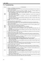
E-50
1. Turn power off and then on again. Press start switch to search home position again.
2. Make sure that X-axis home position sensor and X-axis home position sensor magnet are correctly
attached.
3. Check if connector P1 (ORG) on the control circuit board is correctly inserted and if any harness is
broken or short-circuited.
4. Replace X-axis home position sensor and its harness.
5. Replace the control circuit board with a new one.
E-51
1. Turn power off and then on again. Press start switch to search home position again.
2. Make sure that Y-axis home position sensor and Y-axis home position sensor magnet are correctly
attached.
3. Check if connector P1 (ORG) on the control circuit board is correctly inserted and if any harness is
broken or short-circuited.
4. Replace Y-axis home position sensor and its harness.
5. Replace the control circuit board with a new one.
E-52
1. Turn power off and then on again. Press start switch to search home position again.
2. Make sure that
θ
-axis home position sensor and
θ
-axis home position sensor magnet are correctly
attached.
3. Check if the
θ
-axis home position sensor pulley is loosened.
4. Of connectors relayed to head harness, check if the harness for the
θ
-axis home position sensor is
correctly attached to the connector for the
θ
-axis home position sensor. (The brown harness should
be attached to pin 1, the black one to pin 6, and the blue one to pin 11. Refer to the instruction
manual.)
* Check if there is a harness in the control box that is broken or short-circuited.
5. Check if connector P9 (EXINB) on the control circuit board is correctly inserted and if any harness is
broken or short-circuited.
6. Replace the
θ
-axis home position sensor and its harness with a new one.
7. Replace the control circuit board with a new one.
E-59
1. Turn on the power again.
2. Make sure that ROM chips of the panel circuit board are correctly inserted. (Check position,
orientation, lead clinching, etc.)
3. Initialize memory.
4. Replace the panel circuit board with a new one.
E-60
1. This is not an error. This code indicates machine operation is being suspended due to emergency
stop.
2. Refer to the instruction manual, “Using the EMERGENCY STOP switch.” (Press the RESET switch
to return to home position, and the start switch to resume sewing.)
E-70
1. Turn the pulley manually to see if the upper shaft is not locked.
2. In input mode, turning the pulley manually, check the machine detects needle up signal. If not, refer
to E10. Even if it does, synchronizer harness may be broken or short-circuited. It may appear when
oscillation occurs.
3. With the power turned off, separate connectors P15 (DC300) on the control circuit board, and check
if between pins 1 and 2 in the connector on the board is short-circuited. If it is short-circuited, replace
the control circuit board. At this time, if fuse No.2 on the power supply circuit board has been blown,
replace it.
E-71
Refer to E70. (In input mode, check if the machine detects needle down signal.)
E-72
1. If the knife works correctly, refer to E12. If not, proceed the following steps to check the knife driving
system. (This is because the place to be checked is different if the failure is with the sensor or driving
system.)
2. Make sure that air is supplied to knife valve unit.
3. Check if there is a broken valve cord around valve unit.
4. Check if connector P4 (AIR) of the control circuit board is correctly inserted and if valve cord is
broken or short-circuited.
5. Replace valve cord with a new one.
6. Replace valve unit with a new one.
7. Replace the control circuit board with a new one.
Содержание RH-981A
Страница 8: ...RH 981A ...
Страница 23: ...2 DISASSEMBLY RH 981A 15 2 7 Needle bar thread take up and zigzag mechanisms 3710Q 3711Q 3709Q 3708Q ...
Страница 92: ...5 POWER SUPPLY EQUIPMENT RH 981A 84 Control circuit board Power supply circuit board 3530Q 3531Q ...
Страница 119: ...6 AIR PRESSURE MECHANISM RH 981A 111 5 Cloth opener cylinder 6 Lower thread trimming cylinder 3554Q 3555Q ...
Страница 136: ...7 SOFTWARE RH 981A 128 7 6 Control circuit block diagram 1 3842Q ...
Страница 137: ...7 SOFTWARE RH 981A 129 7 7 Control circuit block diagram 2 3843Q ...
Страница 138: ...SERVICE MANUAL Printed in Japan RH 981A I3080846H 2003 10 H 1 http www brother com ...


