


6-1
6.1 DISASSEMBLY/REASSEMBLY
Safety Precautions
To prevent the creation of secondary problems by mishandling, observe the following precautions
for maintenance work.
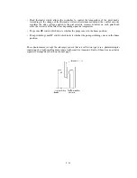
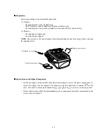
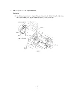
(1) If you unpack the package sent
from the user, first check that the
top edge of the head wiper is
flush with that of the head cap
unit before turning on the
machine. If the head wiper
protrudes or is out of place,
lightly pull up the head wiper and
move it towards the head cap unit
to retract it.
Head cap unit
Head wiper
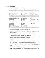
(2) Unplug the power cord from the power outlet before replacing parts or units. When having
access to the power supply, be sure to unplug the power cord from the power outlet.
(3) Be careful not to lose screws, washers, or other parts removed for parts replacement.
(4) Do not remove gears from the document feed roller ASSY (shown on page 6-14) or document
ejection roller ASSY (shown on page 6-19) if at all possible. Once removed, they will become
unusable and new gears will have to be put back in.
(5) When using soldering irons and other heat-generating tools, take care not to damage the resin
parts such as wires, PCBs, and covers.
(6) Before handling the PCBs, touch a metal portion of the machine to discharge static electricity;
otherwise, the electronic parts may be damaged due to the electricity charged in your body.
(7) When transporting PCBs, be sure to wrap them in conductive sheets such as aluminum foil.
(8) Be sure to reinsert self-tapping screws correctly, if removed.
(9) Tighten screws to the torque values listed on the following pages.
(10) When connecting or disconnecting cable connectors, hold the connector bodies not the cables.
If the connector has a lock, always slide the connector lock to unlock it.
(11) Before reassembly, apply the specified lubricant to the specified points. (Refer to Subsection
6.2 in this chapter.)
(12) After repairs, check not only the repaired portion but also that the connectors and other related
portions function properly before operation checks.
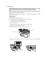
(13) Once the print head unit prints, it will start head locking operation after five seconds from the
end of printing. The head locking operation will take 5 to 10 seconds. NEVER unplug the
power cord before the machine completes the head locking operation; doing so will make the
print head unit unusable and require replacement with a new print head unit.
When you receive the machine from the user or when you pack it for sending it back to the
user, check the head locking state.
Содержание MFC-5200C
Страница 1: ...FACSIMILE EQUIPMENT SERVICE MANUAL MODEL MFC5200C MFC890 ...
Страница 7: ...CHAPTER 1 PARTS NAMES FUNCTIONS ...
Страница 8: ...CHAPTER 1 PARTS NAMES FUNCTIONS CONTENTS 1 1 EQUIPMENT OUTLINE 1 1 1 2 CONTROL PANEL 1 3 ...
Страница 13: ...CHAPTER 2 SPECIFICATIONS ...
Страница 18: ...2 4 2 1 4 Environmental Condition ...
Страница 23: ...CHAPTER 3 INSTALLATION ...
Страница 26: ...3 2 3 2 UNPACKING THE MACHINE The equipment consists of the following major components ...
Страница 34: ...CHAPTER 4 THEORY OF OPERATION ...
Страница 54: ...CHAPTER 5 MAINTENANCE ...
Страница 60: ...CHAPTER 6 DISASSEMBLY REASSEMBLY LUBRICATION AND ADJUSTMENT ...
Страница 141: ...6 79 2 Separation roller and document feed roller 3 Document ejection roller ...
Страница 146: ...6 84 11 Purge shaft EM4 Main chassis ...
Страница 147: ...6 85 12 Carriage Viewed from the rear After lubrication more this to the right and left Carriage EM2 EM4 EM4 EM3 EM3 ...
Страница 151: ...CHAPTER 7 MAINTENANCE MODE ...
Страница 160: ...7 8 Scanning Compensation Data List ...
Страница 174: ...7 22 Vertical Alignment Check Pattern ...
Страница 176: ...7 24 Paper Feeding Check Patterns for the Paper Feed Roller and Paper Ejection Roller Pattern A Pattern B ...
Страница 183: ...CHAPTER 8 ERROR INDICATION AND TROUBLESHOOTING ...
Страница 213: ...8 29 4 Close the manual feed cover ...
Страница 214: ...MFC5200C MFC890 Appendix 1 Serial No Descriptions ...
Страница 215: ...SERIAL NO DESCRIPTIONS The descriptions as below shows how to read labels on each place 1 SET Location ...
Страница 216: ... 2 PRINTER HEAD UNIT Location ...
Страница 228: ...MFC5200C MFC890 Appendix 3 EEPROM Customizing Codes ...
Страница 231: ...MFC5200C MFC890 Appendix 4 Firmware Switches WSW ...
Страница 274: ...MFC5200C MFC890 Appendix 5 Re Packing Instructions ...
Страница 276: ... 8 Place the machine in the original box with the original packaging material ...
Страница 277: ...MFC5200C MFC890 Appendix 6 Wiring Diagram ...
Страница 280: ...A Main PCB 1 4 MFC5200C ...
Страница 281: ...A Main PCB 2 4 MFC5200C ...
Страница 282: ...A Main PCB 3 4 MFC5200C ...
Страница 283: ...A Main PCB 4 4 MFC5200C ...
Страница 284: ...B Driver PCB 1 2 ...
Страница 285: ...B Driver PCB 2 2 ...
Страница 286: ...C NCU PCB MFC5200C ...
Страница 287: ...D Control Panel PCB 1 2 MFC5200C ...
Страница 288: ...D Control Panel PCB 1 2 MFC890 ...
Страница 289: ...D Control Panel PCB 2 2 ...
Страница 290: ...E Power Supply PCB MFC5200C ...
Страница 291: ...F Carriage PCB ...
Страница 292: ...G Media PCB 1 2 ...
Страница 293: ...G Media PCB 2 2 ...
Страница 294: ...Aug 02 SM FAX013 1 8CA503 Printed in Japan ...


