


App. 4-35
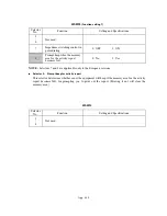
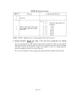
WSW36
(Function setting 14)
Selector
No.
Function
Setting and Specifications
1
ECP mode*
0: ON
1:
OFF
2
Recovery from Inactive PC
Interface
0: Disabled
1:
Enabled
3
PC Power-off Recognition
Time
0: Normal
1:
Long
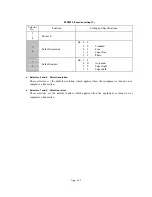
4
Not used.
5
Escape from phase C
0: Yes
1:
No
6
|
8
Lower limit of frequency to be
ignored after detection of
calling signals (Ci)
No. 6 7 8
0 0 0 :
0 (Not ignored)
0 0 1 :
4 (448 Hz)
0 1 0 :
8 (244 Hz)
0 1 1 :
12 (162 Hz)
1 0 0 :
16 (122 Hz)
1 0 1 :
20 (97 Hz)
1 1 0 :
24 (81 Hz)
1 1 1 :
28 (69 Hz)
*ECP (Enhanced Capabilities Port)
Selector 1:
ECP mode
The ECP mode enhances the normal bidirectional communications between the facsimile
equipment and the connected PC for higher transmission speed.
Selector 2:
Recovery from Inactive PC Interface
If the facsimile equipment recognizes via the STB signal line that the connected PC is powered off,
it will turn the PC interface outputs Low to protect the PC from hazards that could be caused by
weak electric current accidentally flown from the equipment.
This selector determines whether the equipment should recover from the inactive PC interface to
normal interfacing state upon receipt of data from the PC.
Selector 3:
PC Power-off Recognition Time
This selector sets the time length from when the equipment detects the PC powered off until it
recognizes the detected state as power-off.
If selector 2 is set to "0," it is recommended that selector 3 be set to "1"; otherwise, the equipment
may mistakenly detect PC powered off.
Selector 5:
Escape from phase C
This selector determines whether or not the equipment will escape from phase C when it detects an
RTC (Return to Control) in non-ECM mode or an RCP (Return to Control Partial page) in ECM
mode.
Содержание MFC-5200C
Страница 1: ...FACSIMILE EQUIPMENT SERVICE MANUAL MODEL MFC5200C MFC890 ...
Страница 7: ...CHAPTER 1 PARTS NAMES FUNCTIONS ...
Страница 8: ...CHAPTER 1 PARTS NAMES FUNCTIONS CONTENTS 1 1 EQUIPMENT OUTLINE 1 1 1 2 CONTROL PANEL 1 3 ...
Страница 13: ...CHAPTER 2 SPECIFICATIONS ...
Страница 18: ...2 4 2 1 4 Environmental Condition ...
Страница 23: ...CHAPTER 3 INSTALLATION ...
Страница 26: ...3 2 3 2 UNPACKING THE MACHINE The equipment consists of the following major components ...
Страница 34: ...CHAPTER 4 THEORY OF OPERATION ...
Страница 54: ...CHAPTER 5 MAINTENANCE ...
Страница 60: ...CHAPTER 6 DISASSEMBLY REASSEMBLY LUBRICATION AND ADJUSTMENT ...
Страница 141: ...6 79 2 Separation roller and document feed roller 3 Document ejection roller ...
Страница 146: ...6 84 11 Purge shaft EM4 Main chassis ...
Страница 147: ...6 85 12 Carriage Viewed from the rear After lubrication more this to the right and left Carriage EM2 EM4 EM4 EM3 EM3 ...
Страница 151: ...CHAPTER 7 MAINTENANCE MODE ...
Страница 160: ...7 8 Scanning Compensation Data List ...
Страница 174: ...7 22 Vertical Alignment Check Pattern ...
Страница 176: ...7 24 Paper Feeding Check Patterns for the Paper Feed Roller and Paper Ejection Roller Pattern A Pattern B ...
Страница 183: ...CHAPTER 8 ERROR INDICATION AND TROUBLESHOOTING ...
Страница 213: ...8 29 4 Close the manual feed cover ...
Страница 214: ...MFC5200C MFC890 Appendix 1 Serial No Descriptions ...
Страница 215: ...SERIAL NO DESCRIPTIONS The descriptions as below shows how to read labels on each place 1 SET Location ...
Страница 216: ... 2 PRINTER HEAD UNIT Location ...
Страница 228: ...MFC5200C MFC890 Appendix 3 EEPROM Customizing Codes ...
Страница 231: ...MFC5200C MFC890 Appendix 4 Firmware Switches WSW ...
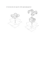
Страница 274: ...MFC5200C MFC890 Appendix 5 Re Packing Instructions ...
Страница 276: ... 8 Place the machine in the original box with the original packaging material ...
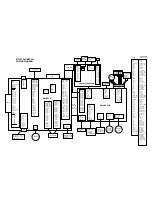
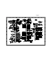
Страница 277: ...MFC5200C MFC890 Appendix 6 Wiring Diagram ...
Страница 280: ...A Main PCB 1 4 MFC5200C ...
Страница 281: ...A Main PCB 2 4 MFC5200C ...
Страница 282: ...A Main PCB 3 4 MFC5200C ...
Страница 283: ...A Main PCB 4 4 MFC5200C ...
Страница 284: ...B Driver PCB 1 2 ...
Страница 285: ...B Driver PCB 2 2 ...
Страница 286: ...C NCU PCB MFC5200C ...
Страница 287: ...D Control Panel PCB 1 2 MFC5200C ...
Страница 288: ...D Control Panel PCB 1 2 MFC890 ...
Страница 289: ...D Control Panel PCB 2 2 ...
Страница 290: ...E Power Supply PCB MFC5200C ...
Страница 291: ...F Carriage PCB ...
Страница 292: ...G Media PCB 1 2 ...
Страница 293: ...G Media PCB 2 2 ...
Страница 294: ...Aug 02 SM FAX013 1 8CA503 Printed in Japan ...


