


8-16
8.2 TROUBLESHOOTING
8.2.1 Introduction
This section gives the service personnel some of the troubleshooting procedures to be followed if
an error or malfunction occurs with the facsimile equipment. It is impossible to anticipate all of the
possible problems which may occur in future and determine the troubleshooting procedures, so this
section covers some sample problems. However, those samples will help service personnel
pinpoint and repair other defective elements if he/she analyzes and examines them well.
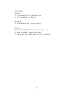
8.2.2 Precautions
Be sure to observe the following to prevent the secondary troubles from happening:
(1) Always unplug the AC power cord from the outlet when removing the covers and PCBs,
adjusting the mechanisms, or conducting continuity testing with a circuit tester.
(2) When disconnecting the connectors, do not pull the lead wires but hold the connector
housings.
(3)
Before handling the PCBs, touch a metal portion of the machine to discharge static
electricity charged in your body.
When repairing the PCBs, handle them with extra care.
After repairing the defective section, be sure to check again if the repaired section works correctly.
Also record the troubleshooting procedure so that it would be of use for future trouble occurrence.
8.2.3 Checking prior to Troubleshooting
Prior to proceeding to the troubleshooting procedures given in Subsection 8.2.4, make the
following initial checks:
Environmental conditions
Check that:
(1) The machine is placed on a flat, firm surface.
(2) The machine is used in a clean environment at or near normal room temperature (10
°
C to
35
°
C) with normal relative humidity (20 to 80%).
(3) The machine is not exposed to direct sunlight or harmful gases.
Power requirements
Check that:
(1) The power supply specified on the rating plate located on the bottom of the machine is used.
The supply voltage stays within the rating ±10%.
(2) Each voltage level on AC input lines and DC lines is correct.
(3) All cables and harnesses are firmly connected.
(4) None of the fuses are blown.
Содержание MFC-5200C
Страница 1: ...FACSIMILE EQUIPMENT SERVICE MANUAL MODEL MFC5200C MFC890 ...
Страница 7: ...CHAPTER 1 PARTS NAMES FUNCTIONS ...
Страница 8: ...CHAPTER 1 PARTS NAMES FUNCTIONS CONTENTS 1 1 EQUIPMENT OUTLINE 1 1 1 2 CONTROL PANEL 1 3 ...
Страница 13: ...CHAPTER 2 SPECIFICATIONS ...
Страница 18: ...2 4 2 1 4 Environmental Condition ...
Страница 23: ...CHAPTER 3 INSTALLATION ...
Страница 26: ...3 2 3 2 UNPACKING THE MACHINE The equipment consists of the following major components ...
Страница 34: ...CHAPTER 4 THEORY OF OPERATION ...
Страница 54: ...CHAPTER 5 MAINTENANCE ...
Страница 60: ...CHAPTER 6 DISASSEMBLY REASSEMBLY LUBRICATION AND ADJUSTMENT ...
Страница 141: ...6 79 2 Separation roller and document feed roller 3 Document ejection roller ...
Страница 146: ...6 84 11 Purge shaft EM4 Main chassis ...
Страница 147: ...6 85 12 Carriage Viewed from the rear After lubrication more this to the right and left Carriage EM2 EM4 EM4 EM3 EM3 ...
Страница 151: ...CHAPTER 7 MAINTENANCE MODE ...
Страница 160: ...7 8 Scanning Compensation Data List ...
Страница 174: ...7 22 Vertical Alignment Check Pattern ...
Страница 176: ...7 24 Paper Feeding Check Patterns for the Paper Feed Roller and Paper Ejection Roller Pattern A Pattern B ...
Страница 183: ...CHAPTER 8 ERROR INDICATION AND TROUBLESHOOTING ...
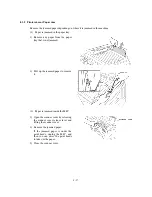
Страница 213: ...8 29 4 Close the manual feed cover ...
Страница 214: ...MFC5200C MFC890 Appendix 1 Serial No Descriptions ...
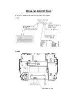
Страница 215: ...SERIAL NO DESCRIPTIONS The descriptions as below shows how to read labels on each place 1 SET Location ...
Страница 216: ... 2 PRINTER HEAD UNIT Location ...
Страница 228: ...MFC5200C MFC890 Appendix 3 EEPROM Customizing Codes ...
Страница 231: ...MFC5200C MFC890 Appendix 4 Firmware Switches WSW ...
Страница 274: ...MFC5200C MFC890 Appendix 5 Re Packing Instructions ...
Страница 276: ... 8 Place the machine in the original box with the original packaging material ...
Страница 277: ...MFC5200C MFC890 Appendix 6 Wiring Diagram ...
Страница 280: ...A Main PCB 1 4 MFC5200C ...
Страница 281: ...A Main PCB 2 4 MFC5200C ...
Страница 282: ...A Main PCB 3 4 MFC5200C ...
Страница 283: ...A Main PCB 4 4 MFC5200C ...
Страница 284: ...B Driver PCB 1 2 ...
Страница 285: ...B Driver PCB 2 2 ...
Страница 286: ...C NCU PCB MFC5200C ...
Страница 287: ...D Control Panel PCB 1 2 MFC5200C ...
Страница 288: ...D Control Panel PCB 1 2 MFC890 ...
Страница 289: ...D Control Panel PCB 2 2 ...
Страница 290: ...E Power Supply PCB MFC5200C ...
Страница 291: ...F Carriage PCB ...
Страница 292: ...G Media PCB 1 2 ...
Страница 293: ...G Media PCB 2 2 ...
Страница 294: ...Aug 02 SM FAX013 1 8CA503 Printed in Japan ...


