


4-16
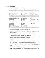
• Head thermister which allows the controller to control the temperature of the print heads.
According to the change of the thermister's internal resistance monitored, the control circuitry
regulates the drive voltage applied to the piezoelectric ceramic actuators on each print head
since the viscosity of the ink varies depending upon the temperature.
• Purge cam HP switch which detects whether the purge cam is in the home position.
• Pump switching cam HP switch which detects whether the pump switching cam is in the home
position.
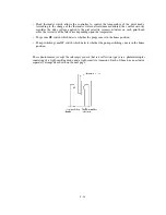
These photosensors (except the ink empty sensor that is a reflection type) are a photointerrupter
consisting of a light-emitting diode and a light-sensitive transistor. Each of them has an actuator
separately arranged as shown on the next page.
Содержание MFC-5200C
Страница 1: ...FACSIMILE EQUIPMENT SERVICE MANUAL MODEL MFC5200C MFC890 ...
Страница 7: ...CHAPTER 1 PARTS NAMES FUNCTIONS ...
Страница 8: ...CHAPTER 1 PARTS NAMES FUNCTIONS CONTENTS 1 1 EQUIPMENT OUTLINE 1 1 1 2 CONTROL PANEL 1 3 ...
Страница 13: ...CHAPTER 2 SPECIFICATIONS ...
Страница 18: ...2 4 2 1 4 Environmental Condition ...
Страница 23: ...CHAPTER 3 INSTALLATION ...
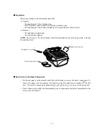
Страница 26: ...3 2 3 2 UNPACKING THE MACHINE The equipment consists of the following major components ...
Страница 34: ...CHAPTER 4 THEORY OF OPERATION ...
Страница 54: ...CHAPTER 5 MAINTENANCE ...
Страница 60: ...CHAPTER 6 DISASSEMBLY REASSEMBLY LUBRICATION AND ADJUSTMENT ...
Страница 141: ...6 79 2 Separation roller and document feed roller 3 Document ejection roller ...
Страница 146: ...6 84 11 Purge shaft EM4 Main chassis ...
Страница 147: ...6 85 12 Carriage Viewed from the rear After lubrication more this to the right and left Carriage EM2 EM4 EM4 EM3 EM3 ...
Страница 151: ...CHAPTER 7 MAINTENANCE MODE ...
Страница 160: ...7 8 Scanning Compensation Data List ...
Страница 174: ...7 22 Vertical Alignment Check Pattern ...
Страница 176: ...7 24 Paper Feeding Check Patterns for the Paper Feed Roller and Paper Ejection Roller Pattern A Pattern B ...
Страница 183: ...CHAPTER 8 ERROR INDICATION AND TROUBLESHOOTING ...
Страница 213: ...8 29 4 Close the manual feed cover ...
Страница 214: ...MFC5200C MFC890 Appendix 1 Serial No Descriptions ...
Страница 215: ...SERIAL NO DESCRIPTIONS The descriptions as below shows how to read labels on each place 1 SET Location ...
Страница 216: ... 2 PRINTER HEAD UNIT Location ...
Страница 228: ...MFC5200C MFC890 Appendix 3 EEPROM Customizing Codes ...
Страница 231: ...MFC5200C MFC890 Appendix 4 Firmware Switches WSW ...
Страница 274: ...MFC5200C MFC890 Appendix 5 Re Packing Instructions ...
Страница 276: ... 8 Place the machine in the original box with the original packaging material ...
Страница 277: ...MFC5200C MFC890 Appendix 6 Wiring Diagram ...
Страница 280: ...A Main PCB 1 4 MFC5200C ...
Страница 281: ...A Main PCB 2 4 MFC5200C ...
Страница 282: ...A Main PCB 3 4 MFC5200C ...
Страница 283: ...A Main PCB 4 4 MFC5200C ...
Страница 284: ...B Driver PCB 1 2 ...
Страница 285: ...B Driver PCB 2 2 ...
Страница 286: ...C NCU PCB MFC5200C ...
Страница 287: ...D Control Panel PCB 1 2 MFC5200C ...
Страница 288: ...D Control Panel PCB 1 2 MFC890 ...
Страница 289: ...D Control Panel PCB 2 2 ...
Страница 290: ...E Power Supply PCB MFC5200C ...
Страница 291: ...F Carriage PCB ...
Страница 292: ...G Media PCB 1 2 ...
Страница 293: ...G Media PCB 2 2 ...
Страница 294: ...Aug 02 SM FAX013 1 8CA503 Printed in Japan ...


