


6-42
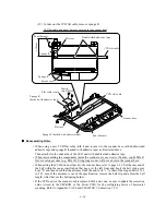
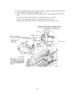
Head flat cable M (main-head power line)
(Optional LAN board)
CCD flat cable
USB
Centronics interface
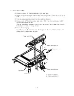
Speaker harness
NCU harness
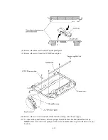
Media flat cable 2 (21-pin)
Media flat cable 1 (22-pin)
Main-driver connector
Manual feed slot cover sensor harness
Main PCB
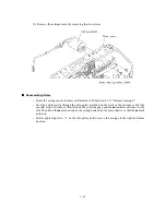
Reassembling Notes
• Be sure to route the speaker harness, NCU harness, and head flat cable M (main-head power
line) as illustrated in Subsection 6.1.31 "Harness routing C."
• If the main PCB is replaced with a new one, be sure to install the update data to the flash ROM
of the new main PCB, referring to Appendix 2, A2.1.
Then make the machine enter the maintenance mode (by pressing the
Menu
,
*
,
2
,
8
,
6
, and
4
keys in this order) after reassembly and then perform the following:
- Sensor operational check [Function code: 32]
- Operational check of control panel PCB [Function code: 13]
- ADF performance test [Function code: 08]
- Operational check of LCD [Function code: 12]
For details about the entry to the maintenance mode, maintenance-mode functions, and exit
from the maintenance mode, refer to CHAPTER 7.
Содержание MFC-5200C
Страница 1: ...FACSIMILE EQUIPMENT SERVICE MANUAL MODEL MFC5200C MFC890 ...
Страница 7: ...CHAPTER 1 PARTS NAMES FUNCTIONS ...
Страница 8: ...CHAPTER 1 PARTS NAMES FUNCTIONS CONTENTS 1 1 EQUIPMENT OUTLINE 1 1 1 2 CONTROL PANEL 1 3 ...
Страница 13: ...CHAPTER 2 SPECIFICATIONS ...
Страница 18: ...2 4 2 1 4 Environmental Condition ...
Страница 23: ...CHAPTER 3 INSTALLATION ...
Страница 26: ...3 2 3 2 UNPACKING THE MACHINE The equipment consists of the following major components ...
Страница 34: ...CHAPTER 4 THEORY OF OPERATION ...
Страница 54: ...CHAPTER 5 MAINTENANCE ...
Страница 60: ...CHAPTER 6 DISASSEMBLY REASSEMBLY LUBRICATION AND ADJUSTMENT ...
Страница 141: ...6 79 2 Separation roller and document feed roller 3 Document ejection roller ...
Страница 146: ...6 84 11 Purge shaft EM4 Main chassis ...
Страница 147: ...6 85 12 Carriage Viewed from the rear After lubrication more this to the right and left Carriage EM2 EM4 EM4 EM3 EM3 ...
Страница 151: ...CHAPTER 7 MAINTENANCE MODE ...
Страница 160: ...7 8 Scanning Compensation Data List ...
Страница 174: ...7 22 Vertical Alignment Check Pattern ...
Страница 176: ...7 24 Paper Feeding Check Patterns for the Paper Feed Roller and Paper Ejection Roller Pattern A Pattern B ...
Страница 183: ...CHAPTER 8 ERROR INDICATION AND TROUBLESHOOTING ...
Страница 213: ...8 29 4 Close the manual feed cover ...
Страница 214: ...MFC5200C MFC890 Appendix 1 Serial No Descriptions ...
Страница 215: ...SERIAL NO DESCRIPTIONS The descriptions as below shows how to read labels on each place 1 SET Location ...
Страница 216: ... 2 PRINTER HEAD UNIT Location ...
Страница 228: ...MFC5200C MFC890 Appendix 3 EEPROM Customizing Codes ...
Страница 231: ...MFC5200C MFC890 Appendix 4 Firmware Switches WSW ...
Страница 274: ...MFC5200C MFC890 Appendix 5 Re Packing Instructions ...
Страница 276: ... 8 Place the machine in the original box with the original packaging material ...
Страница 277: ...MFC5200C MFC890 Appendix 6 Wiring Diagram ...
Страница 280: ...A Main PCB 1 4 MFC5200C ...
Страница 281: ...A Main PCB 2 4 MFC5200C ...
Страница 282: ...A Main PCB 3 4 MFC5200C ...
Страница 283: ...A Main PCB 4 4 MFC5200C ...
Страница 284: ...B Driver PCB 1 2 ...
Страница 285: ...B Driver PCB 2 2 ...
Страница 286: ...C NCU PCB MFC5200C ...
Страница 287: ...D Control Panel PCB 1 2 MFC5200C ...
Страница 288: ...D Control Panel PCB 1 2 MFC890 ...
Страница 289: ...D Control Panel PCB 2 2 ...
Страница 290: ...E Power Supply PCB MFC5200C ...
Страница 291: ...F Carriage PCB ...
Страница 292: ...G Media PCB 1 2 ...
Страница 293: ...G Media PCB 2 2 ...
Страница 294: ...Aug 02 SM FAX013 1 8CA503 Printed in Japan ...


