


CHAPTER 6 DISASSEMBLY/REASSEMBLY, LUBRICATION,
ADJUSTMENT
CONTENTS
6.1
DISASSEMBLY/REASSEMBLY .....................................................................................6-1
Safety Precautions.......................................................................................................6-1
Tightening Torque List......................................................................................................6-2
Preparation ..................................................................................................................6-4
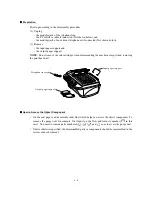
How to Access the Object Component........................................................................6-4
Disassembly Order Flow..............................................................................................6-5
6.1.1
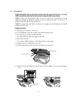
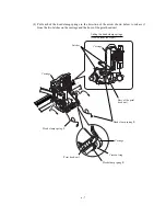
Print Head Unit .....................................................................................................6-6
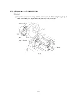
6.1.2
ADF Cover and Document Guide Base .............................................................6-12
6.1.3
ADF Components on the Upper ADF Chute......................................................6-13
6.1.4
ADF Components on the Lower ADF Chute......................................................6-18
6.1.5
Document Cover Open Sensor and ADF Document Output Support
Extension............................................................................................................6-23
6.1.6
Manual Feed Slot Cover and Rear Cover..........................................................6-24
6.1.7
Main PCB Shield Case and Scanner Unit (Together with Document Cover) ....6-25
6.1.8
Control Panel ASSY...........................................................................................6-30
6.1.9
Disassembly of the Control Panel ASSY ...........................................................6-31
6.1.10 Disassembly of the Scanner Unit .......................................................................6-32
6.1.11 Edge Cover, Scanner Links and Their Guides...................................................6-37
6.1.12 Main Cover .........................................................................................................6-38
6.1.13 Media Module (Media Cover, Media PCB, and Frame) and Media Flat
Cables ................................................................................................................6-39
6.1.14 Main PCB and its Shield Frame.........................................................................6-41
6.1.15 ASF and ASF roller ASSY..................................................................................6-43
6.1.16 FG Plates, Power Supply PCB, and NCU PCB .................................................6-45
6.1.17 Speaker ..............................................................................................................6-47
6.1.18 Purge Unit ..........................................................................................................6-48
6.1.19 Driver PCB .........................................................................................................6-50
Содержание MFC-5200C
Страница 1: ...FACSIMILE EQUIPMENT SERVICE MANUAL MODEL MFC5200C MFC890 ...
Страница 7: ...CHAPTER 1 PARTS NAMES FUNCTIONS ...
Страница 8: ...CHAPTER 1 PARTS NAMES FUNCTIONS CONTENTS 1 1 EQUIPMENT OUTLINE 1 1 1 2 CONTROL PANEL 1 3 ...
Страница 13: ...CHAPTER 2 SPECIFICATIONS ...
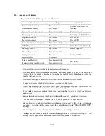
Страница 18: ...2 4 2 1 4 Environmental Condition ...
Страница 23: ...CHAPTER 3 INSTALLATION ...
Страница 26: ...3 2 3 2 UNPACKING THE MACHINE The equipment consists of the following major components ...
Страница 34: ...CHAPTER 4 THEORY OF OPERATION ...
Страница 54: ...CHAPTER 5 MAINTENANCE ...
Страница 60: ...CHAPTER 6 DISASSEMBLY REASSEMBLY LUBRICATION AND ADJUSTMENT ...
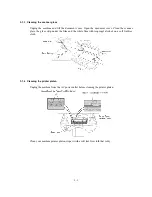
Страница 141: ...6 79 2 Separation roller and document feed roller 3 Document ejection roller ...
Страница 146: ...6 84 11 Purge shaft EM4 Main chassis ...
Страница 147: ...6 85 12 Carriage Viewed from the rear After lubrication more this to the right and left Carriage EM2 EM4 EM4 EM3 EM3 ...
Страница 151: ...CHAPTER 7 MAINTENANCE MODE ...
Страница 160: ...7 8 Scanning Compensation Data List ...
Страница 174: ...7 22 Vertical Alignment Check Pattern ...
Страница 176: ...7 24 Paper Feeding Check Patterns for the Paper Feed Roller and Paper Ejection Roller Pattern A Pattern B ...
Страница 183: ...CHAPTER 8 ERROR INDICATION AND TROUBLESHOOTING ...
Страница 213: ...8 29 4 Close the manual feed cover ...
Страница 214: ...MFC5200C MFC890 Appendix 1 Serial No Descriptions ...
Страница 215: ...SERIAL NO DESCRIPTIONS The descriptions as below shows how to read labels on each place 1 SET Location ...
Страница 216: ... 2 PRINTER HEAD UNIT Location ...
Страница 228: ...MFC5200C MFC890 Appendix 3 EEPROM Customizing Codes ...
Страница 231: ...MFC5200C MFC890 Appendix 4 Firmware Switches WSW ...
Страница 274: ...MFC5200C MFC890 Appendix 5 Re Packing Instructions ...
Страница 276: ... 8 Place the machine in the original box with the original packaging material ...
Страница 277: ...MFC5200C MFC890 Appendix 6 Wiring Diagram ...
Страница 280: ...A Main PCB 1 4 MFC5200C ...
Страница 281: ...A Main PCB 2 4 MFC5200C ...
Страница 282: ...A Main PCB 3 4 MFC5200C ...
Страница 283: ...A Main PCB 4 4 MFC5200C ...
Страница 284: ...B Driver PCB 1 2 ...
Страница 285: ...B Driver PCB 2 2 ...
Страница 286: ...C NCU PCB MFC5200C ...
Страница 287: ...D Control Panel PCB 1 2 MFC5200C ...
Страница 288: ...D Control Panel PCB 1 2 MFC890 ...
Страница 289: ...D Control Panel PCB 2 2 ...
Страница 290: ...E Power Supply PCB MFC5200C ...
Страница 291: ...F Carriage PCB ...
Страница 292: ...G Media PCB 1 2 ...
Страница 293: ...G Media PCB 2 2 ...
Страница 294: ...Aug 02 SM FAX013 1 8CA503 Printed in Japan ...


